Your Cart is Empty


FOR TOYOTA TACOMA MODEL
PARTS INCLUDED:1 x Automatic Control Box
2 x Connection Plate
2 x Power Fold Actuator
2 x Actuator Wire Harness
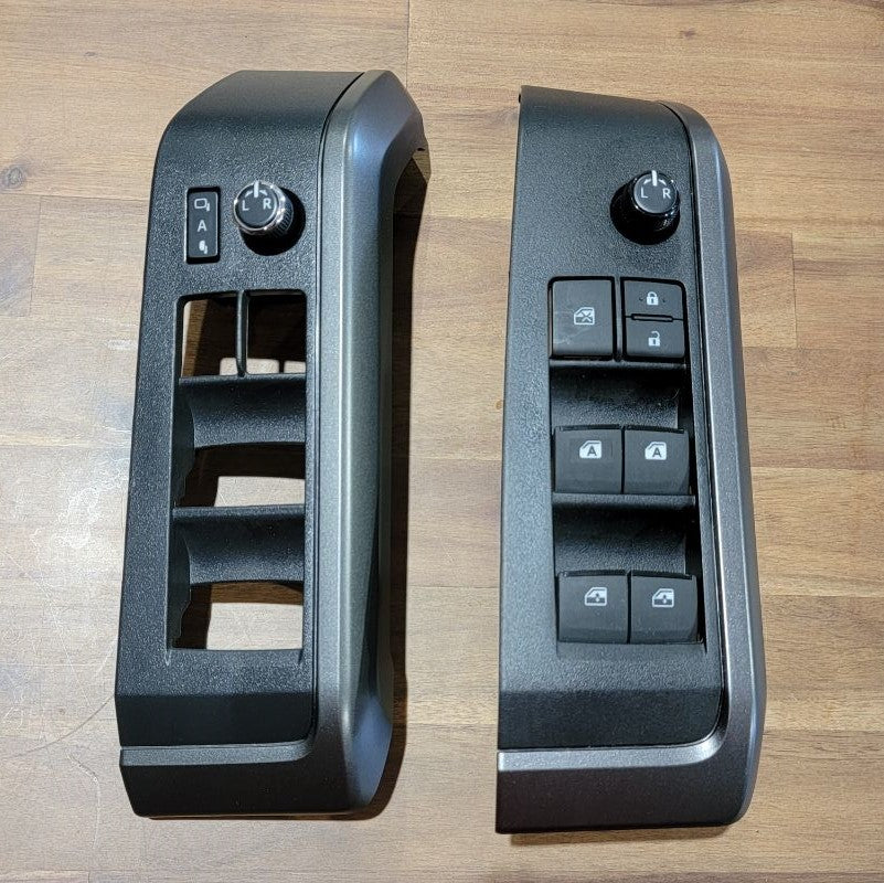
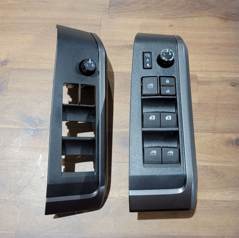
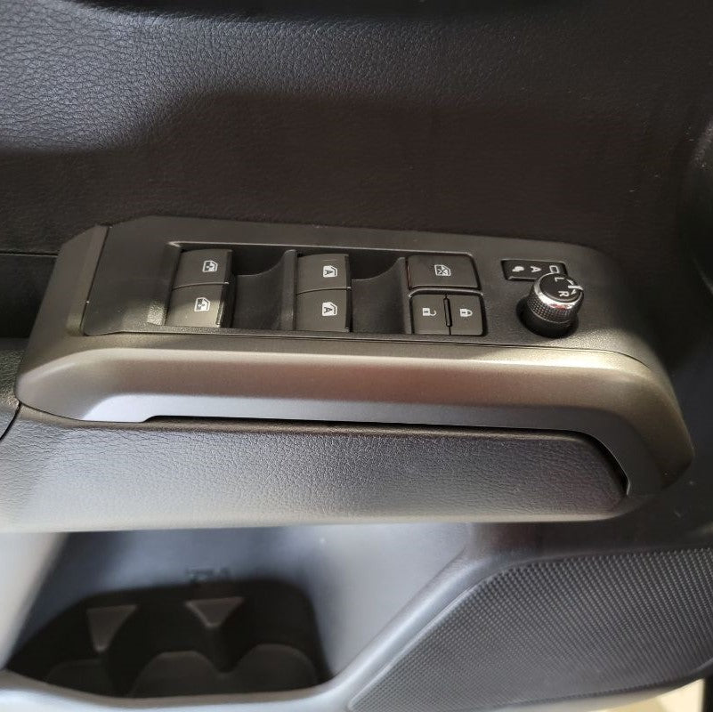
1 x Adjust & Fold Switch
1 x Adjust & Fold Switch Harness
2 x Extension Wire Harness - Driver Side (Shorter) / Passenger Side (Longer)
ADDITIONAL PACKAGE CONTENTS INCLUDED:1 x Hardware Bag
1 x 3M, Double-Sided Adhesive Sheet
1 x Tool, Trim Removal
TOOLS NOT INCLUDED BUT ARE NEEDED:Installation Instructions - Power Folding Mirrors (Located on Website)
1/2-in Socket (10 mm)
1/2-in Drive Ratchet
Phillips Screw Driver
1 x 1/8-in Flat Head Screwdriver (optional)
1 x Fish Tape Wire Puller (optional)
Electrical Tape (optional)
Zip Ties (optional)
Door Panel Remover (optional)
DISCONNECT THE BATTERY BEFORE YOU BEGIN INSTALLATION
Must Press + to see the narrative on each Step
-
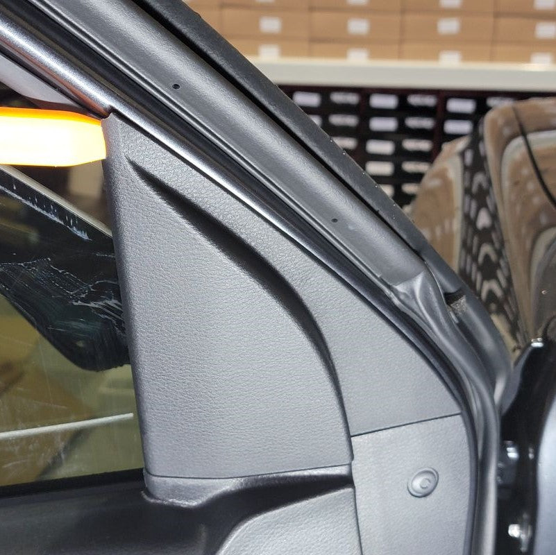
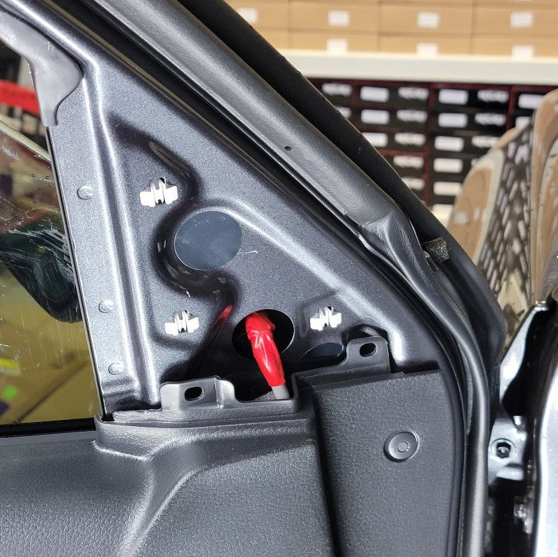
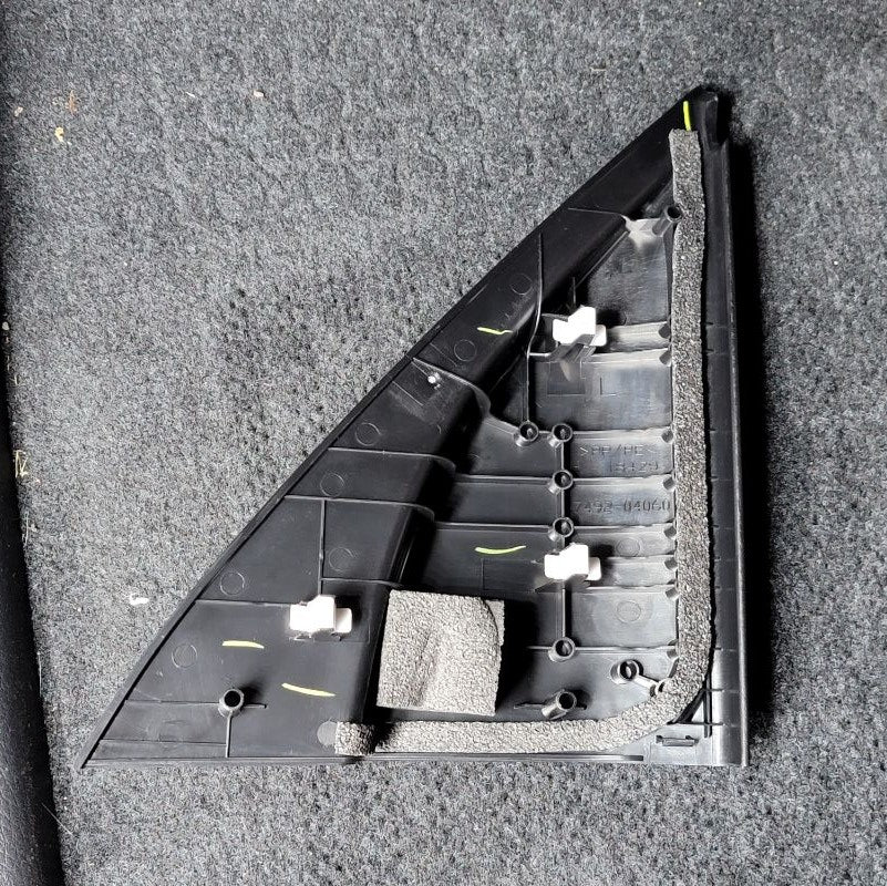
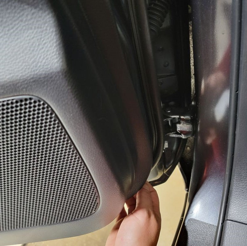
Start by removing the triangle trim panel in the upper right corner of your door. It is held in with three plastic fasteners. Pull straight out away from the door and it will release. Be aware, some of the white plastic fasteners may stay in the door. Remove these and reinstall them on the trim panel for reinstallation later.
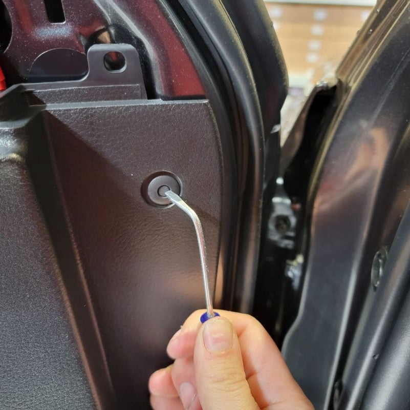
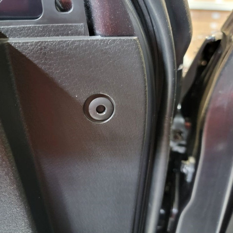
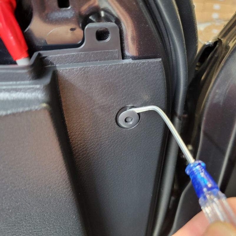
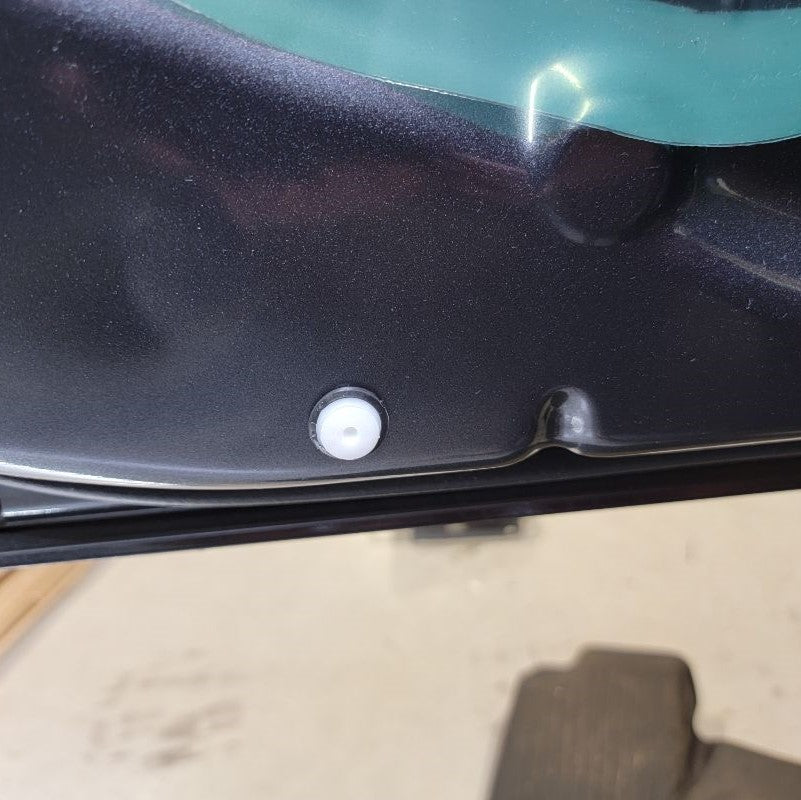
Following that, you will have one small circled fastener located right below the triangle trim piece you just removed. Push the center of that fastener inward to release it from the back of the door panel. Grab the outside of the circle fastener and it should release when you pull it out of the panel.
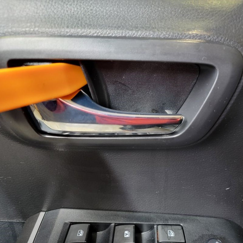
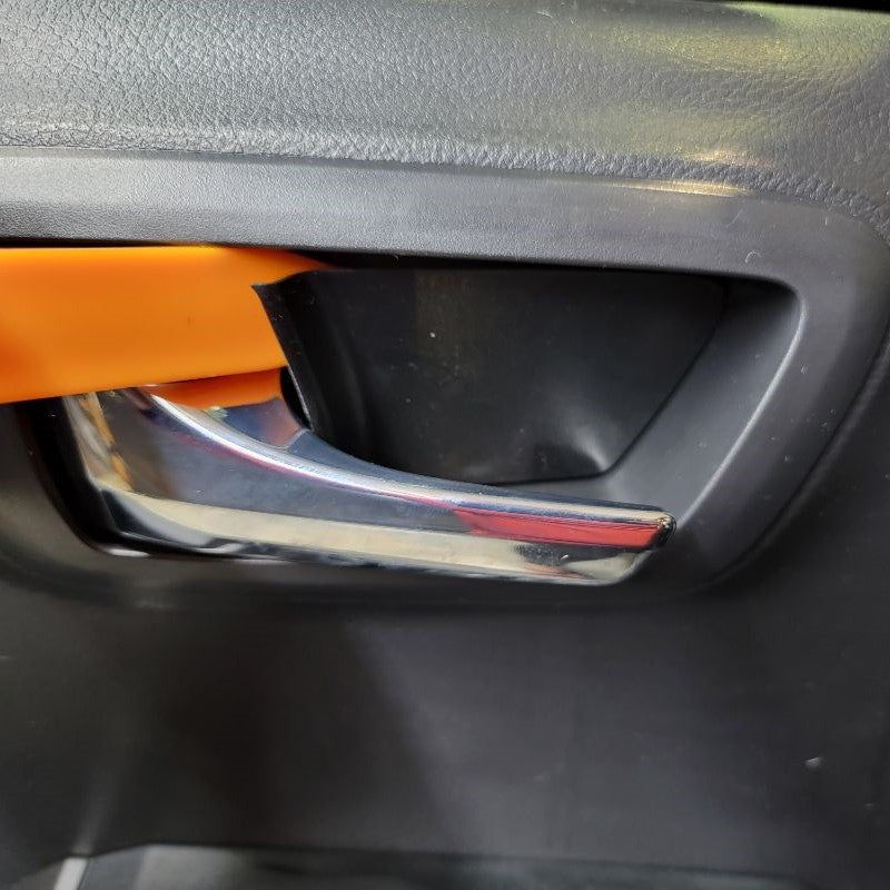
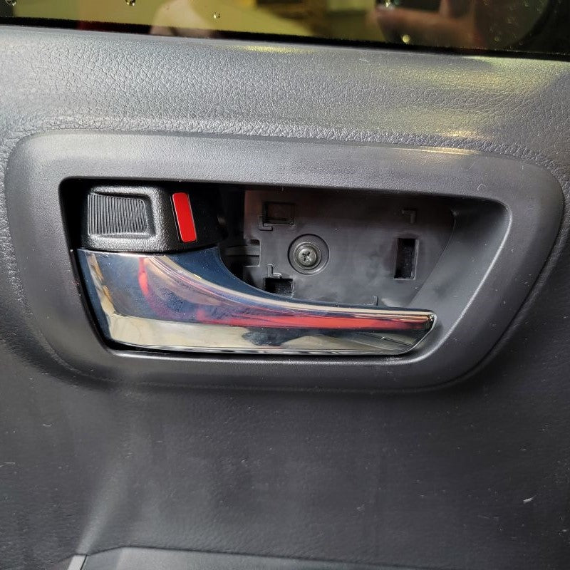
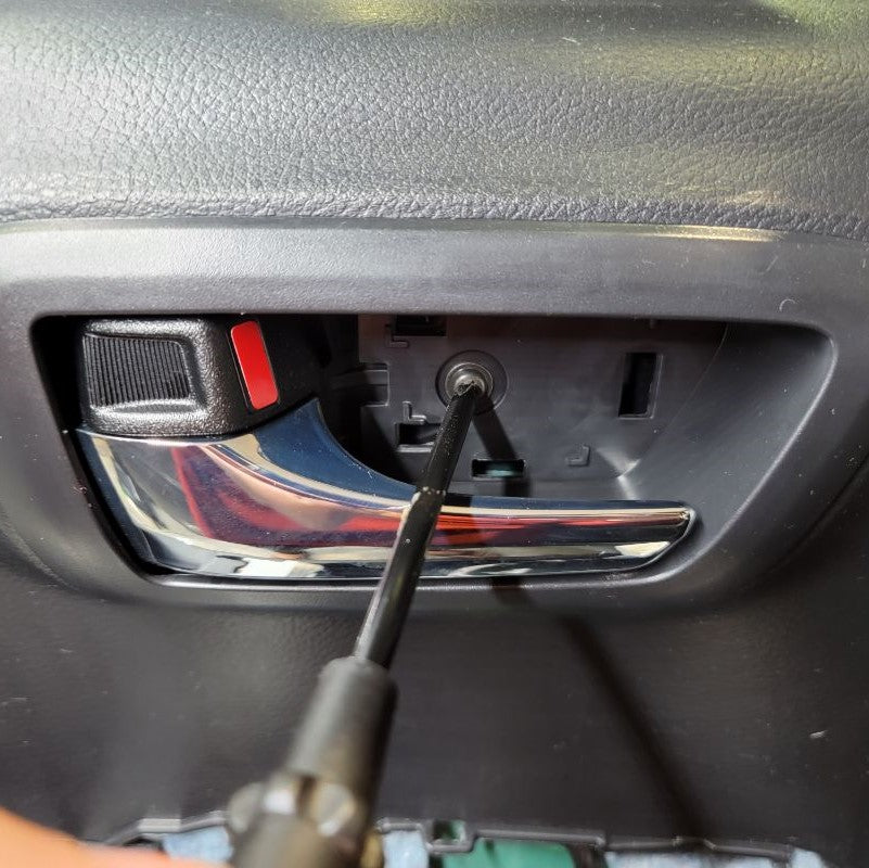
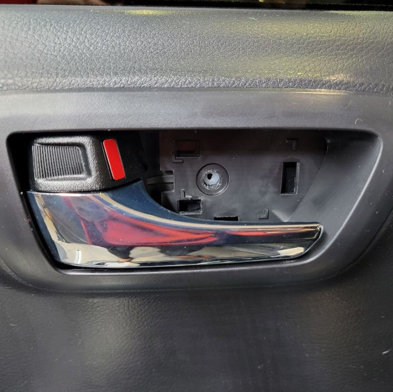
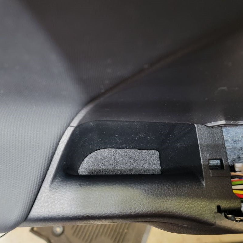
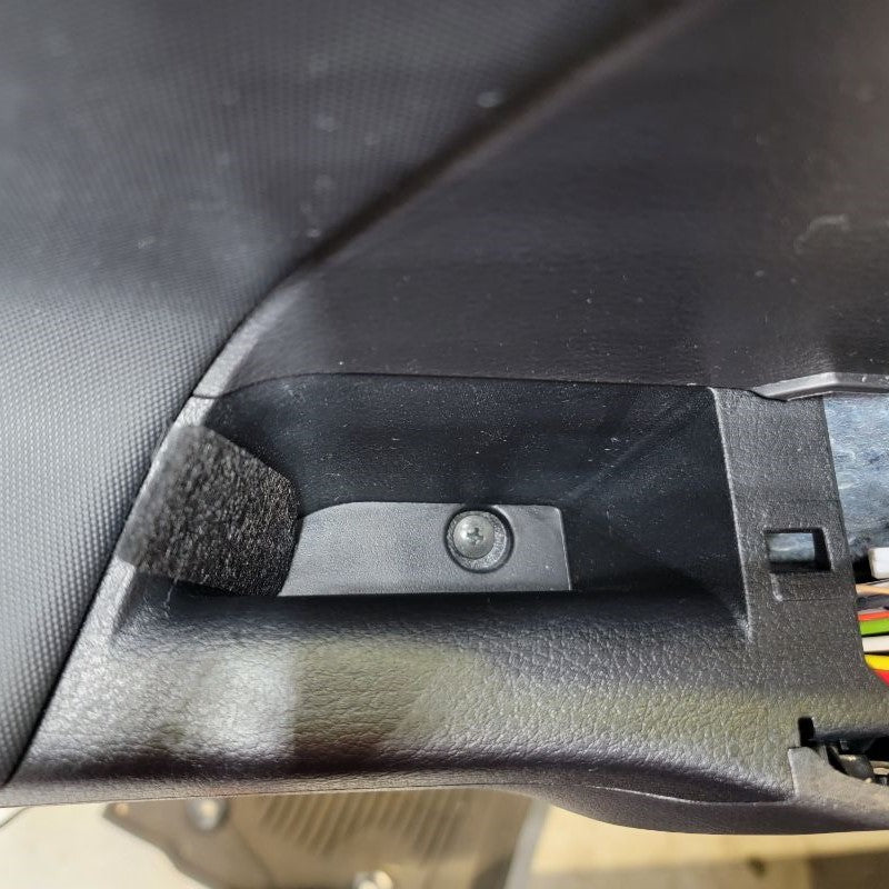
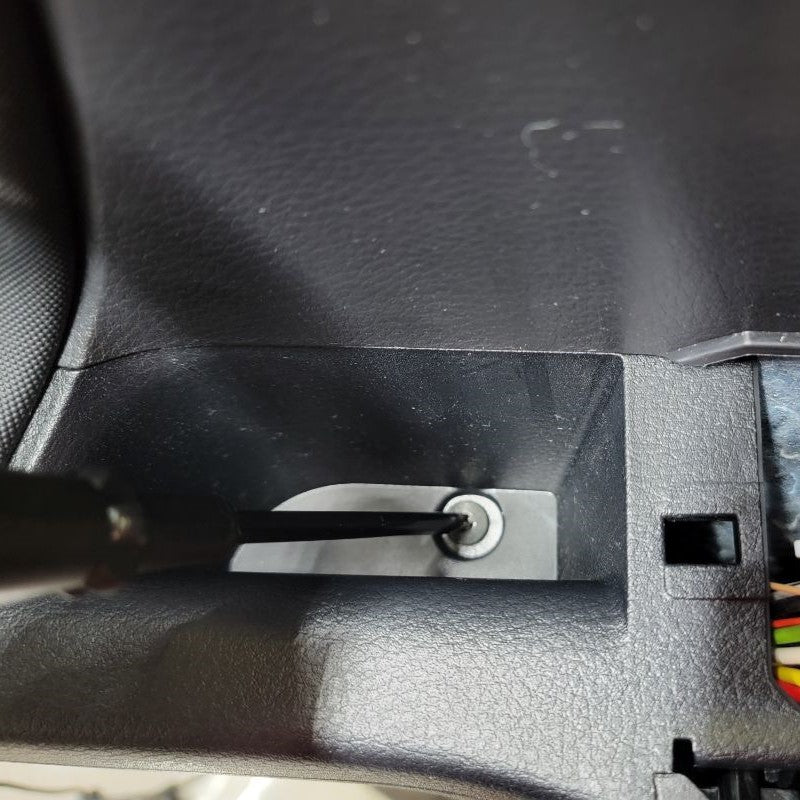
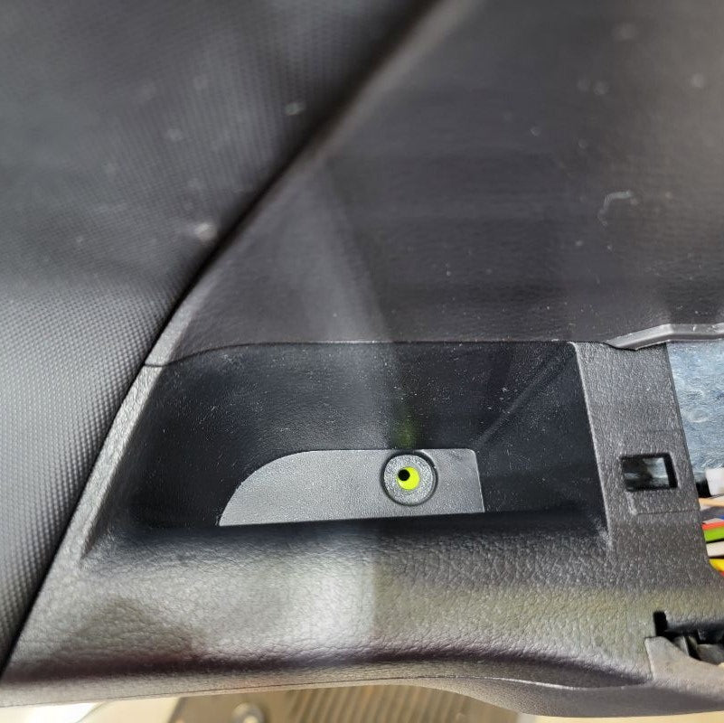
Next, as you continue to slide down the door panel, remove the door bowl hole cover by using a trim removal tool if you have one or something like it. Start on the left side closest to the door handle. Pry outward away from the door panel from behind the hole cover. It may be easier to pull the door handle out to create more space. Behind the hole cover, you will notice your first hidden screw. Take a screw driver and remove that screw. Set it aside for now.
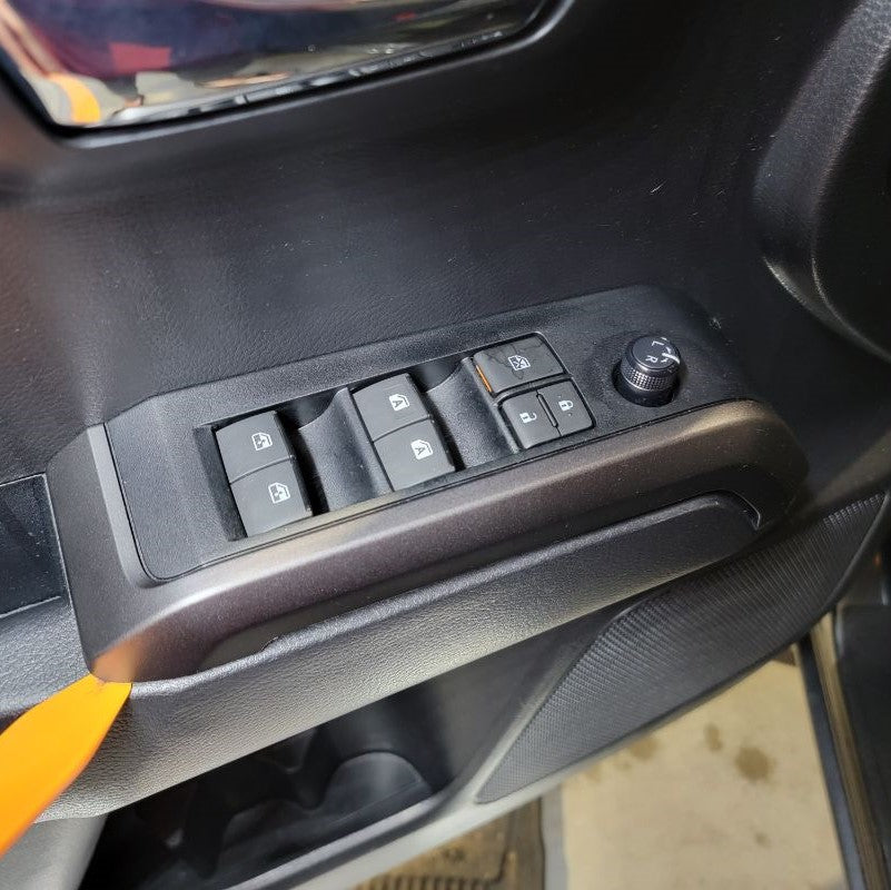
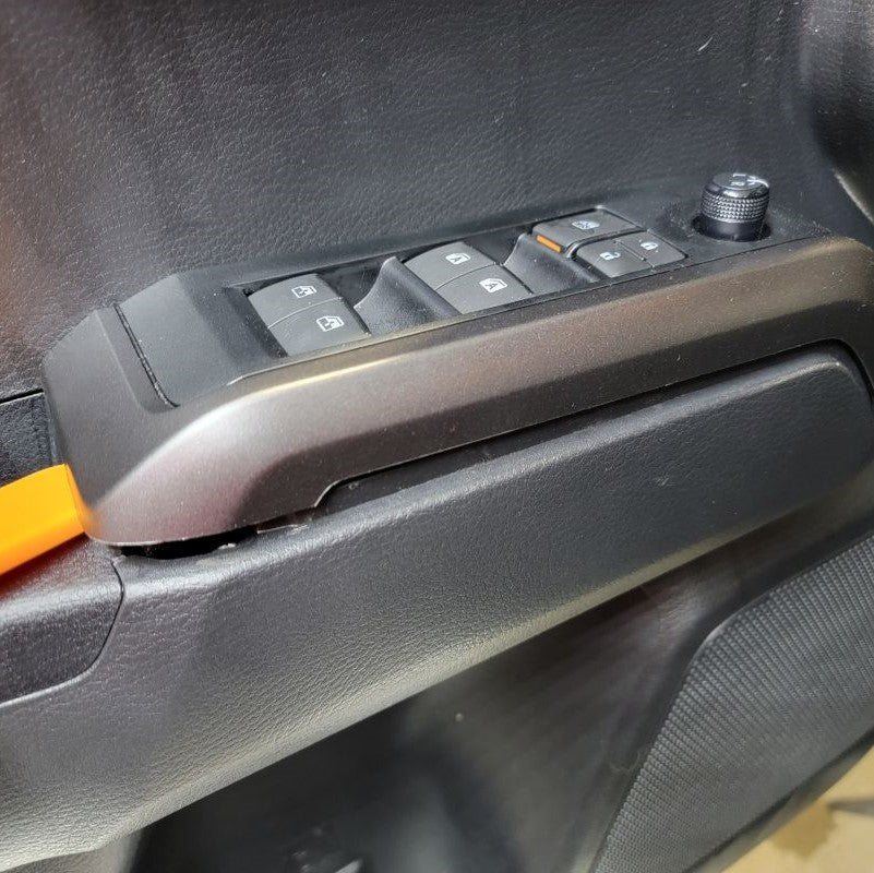
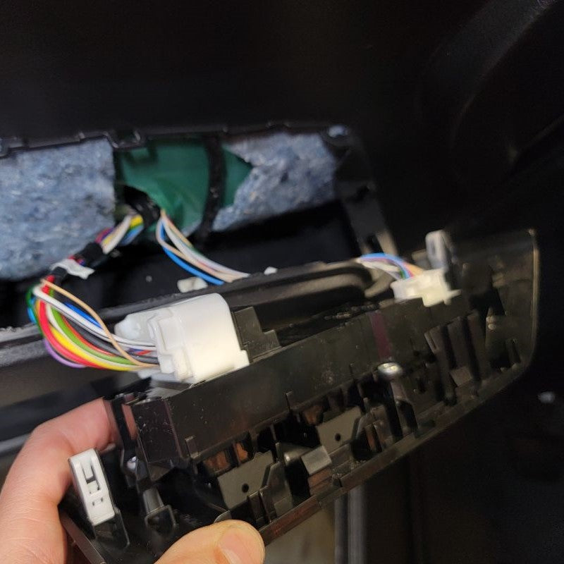
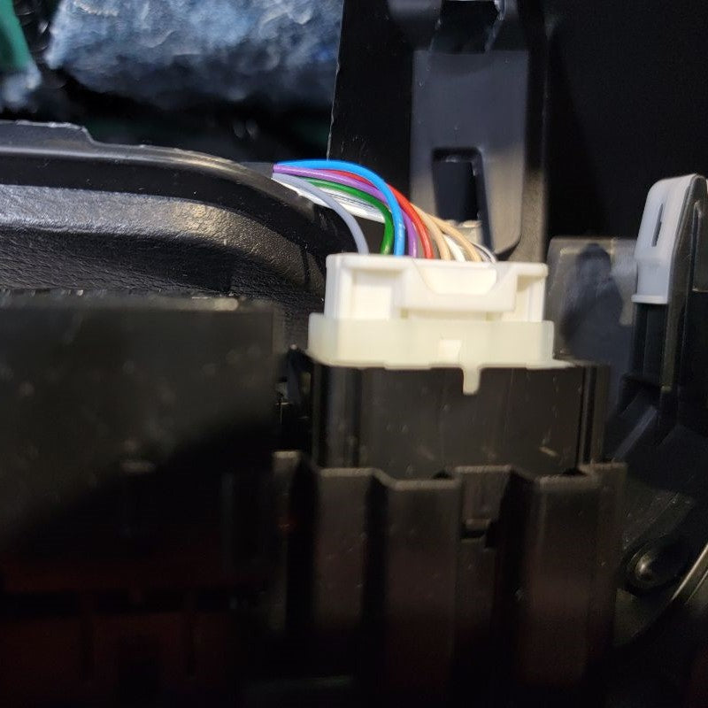
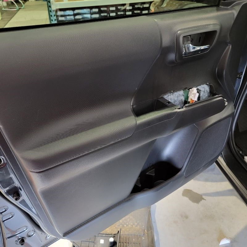
Lastly, in preparing the door panel for removal, you will need to remove the window switch trim panel. Again, using a trim removal tool or something like, pry upward to release the tabs from the door panel underneath. Disconnect the factory connectors at this point and set the window switch panel aside. Along side of the window switch panel, remove the carpet that is located in the door panel armrest handle pull pocket. Hidden underneath the carpet, you will see another screw. Remove that screw and set it aside for now.
STEP 1
INSTALL IMAGES


STEP 2
-
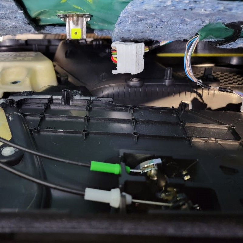
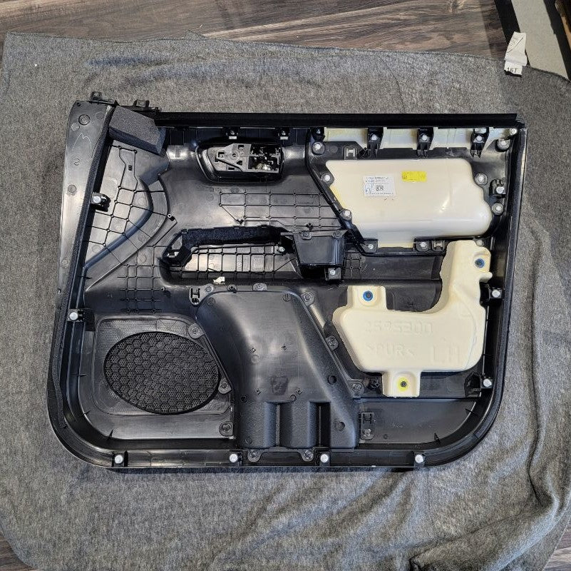
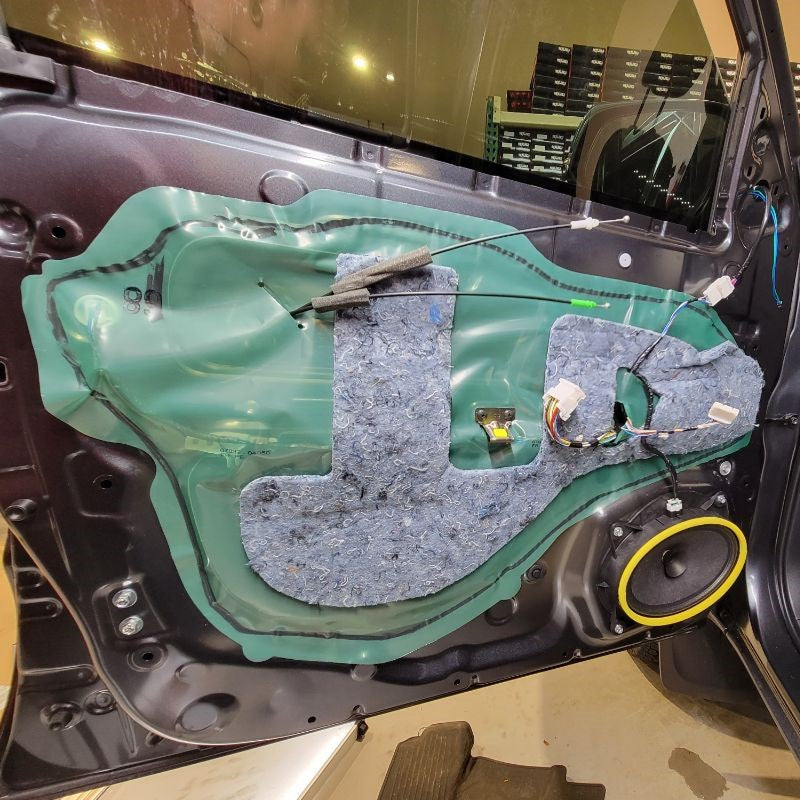
Using your handy trim removal tool or just your hand, begin in the lower right corner and start separating the door panel from the door frame. Slowly work your way around the bottom and sides, popping off each successive snap until you’re left with the door panel hanging by the top lip.
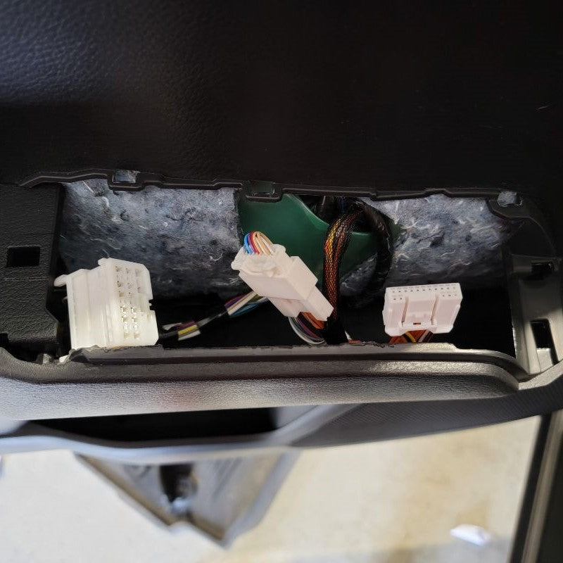
Before trying to lift and pull off the door panel completely, disconnect and remove all the connections on the backside of the panel.
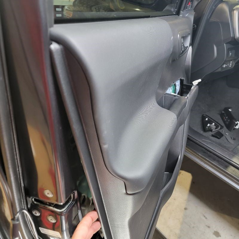
Now, in order to remove the door panel, pull it up and straight back off the door frame at the top lip. Make sure not to pull the door panel too far away from the frame – we still need to deal with the latch and lock cables and a couple other connections.
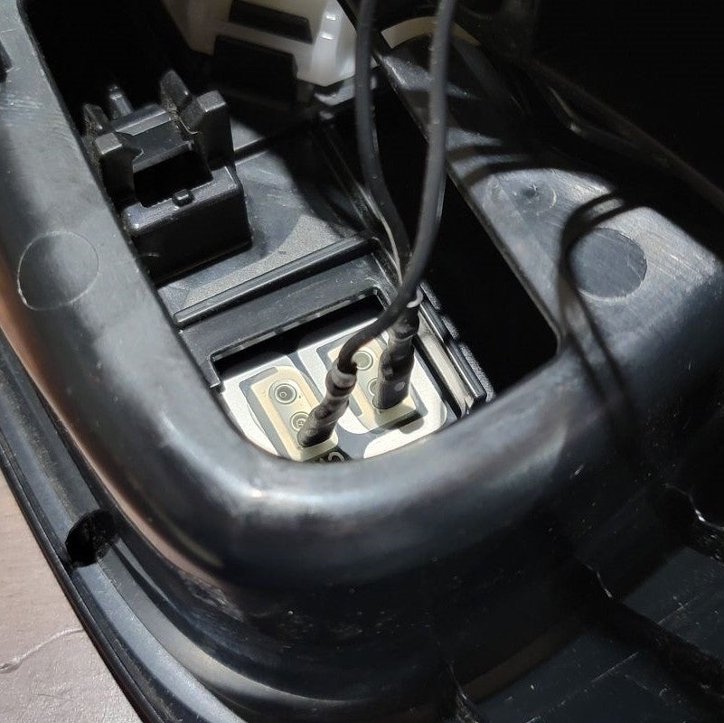
If you look behind the door panel you just pulled off, you’ll see one white and one green Bowden Cable termination. Carefully snap these out of the black housing and maneuver the steel cable ends out of their enclosures.
Finally, unplug the white connector towards the front of the door panel as it is the last connector that is standing in the way of removing the door panel completely from the door frame.
INSTALL IMAGES


STEP 3
-
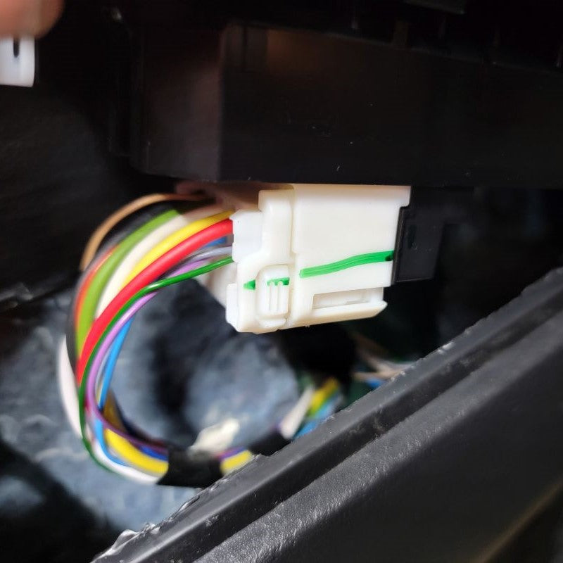
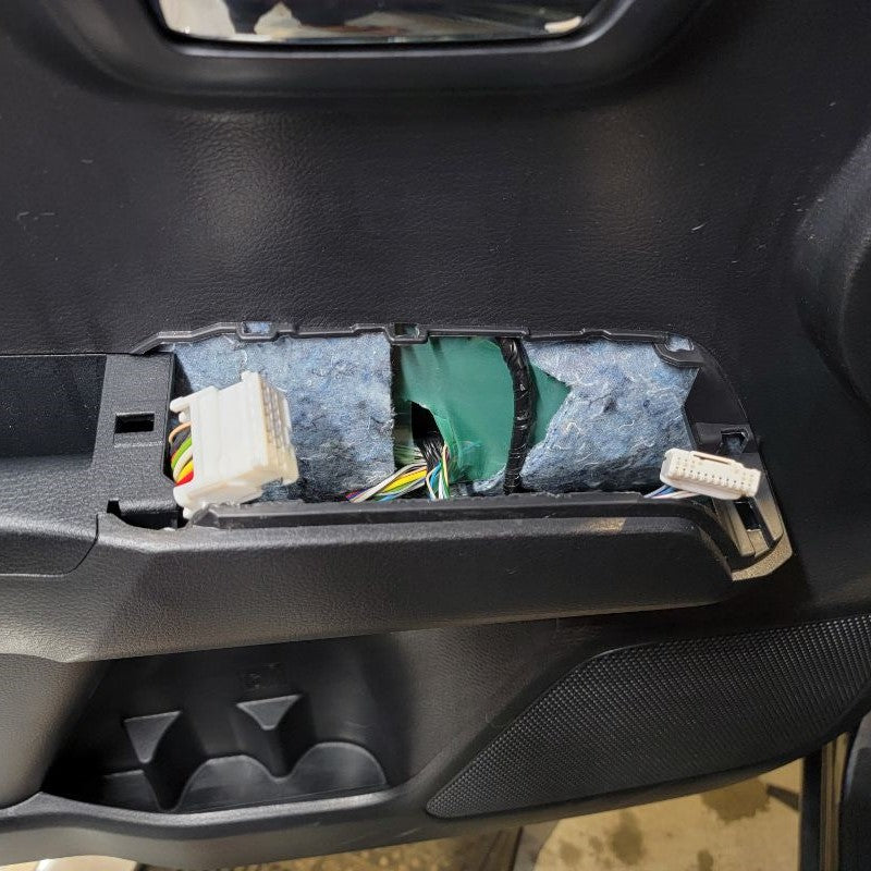
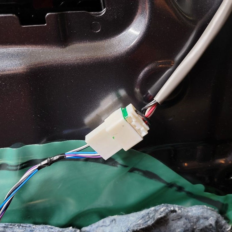
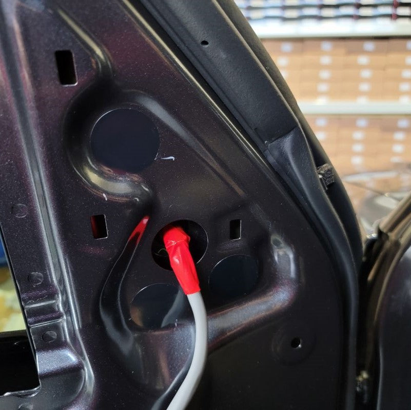
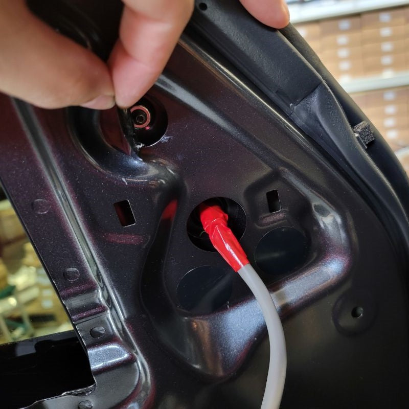
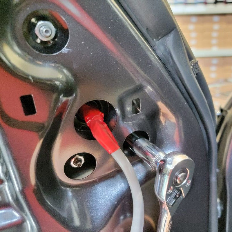
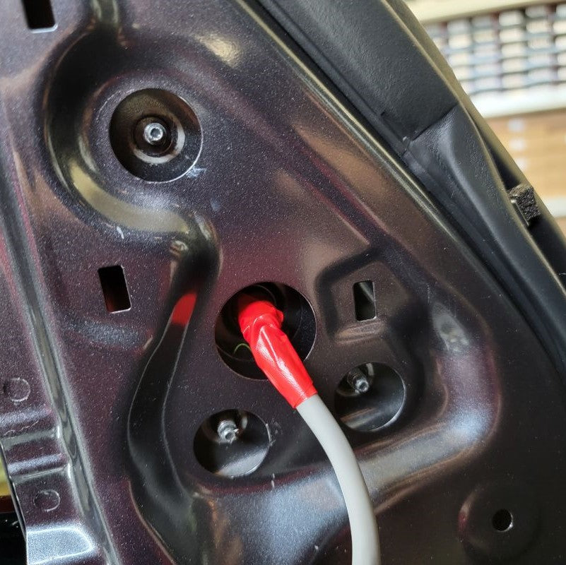
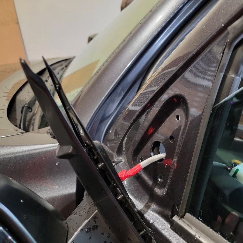
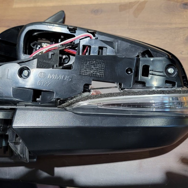
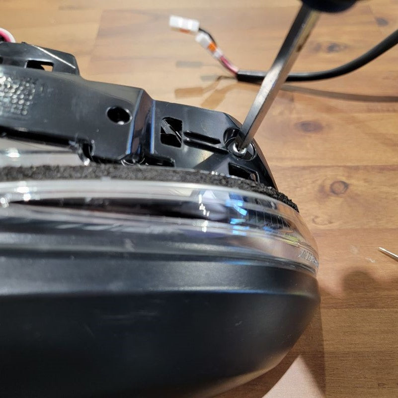
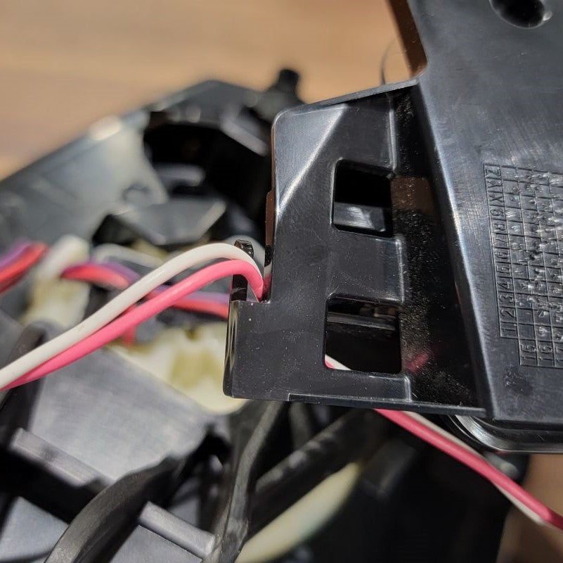
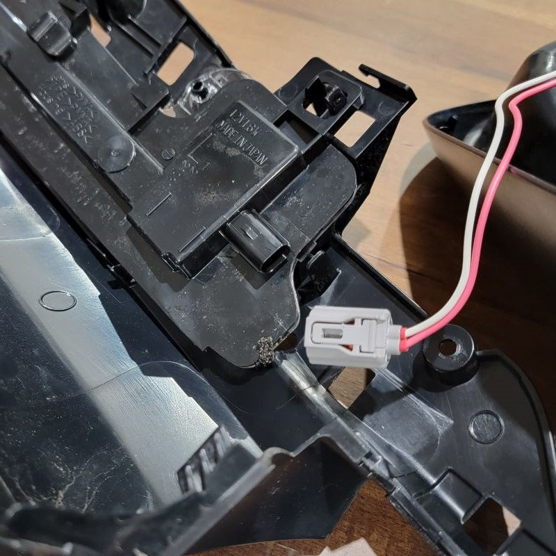
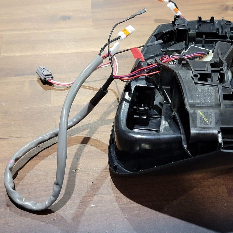
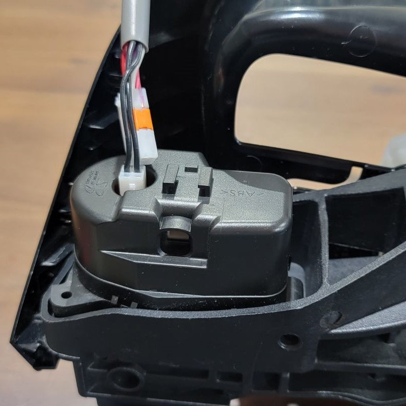
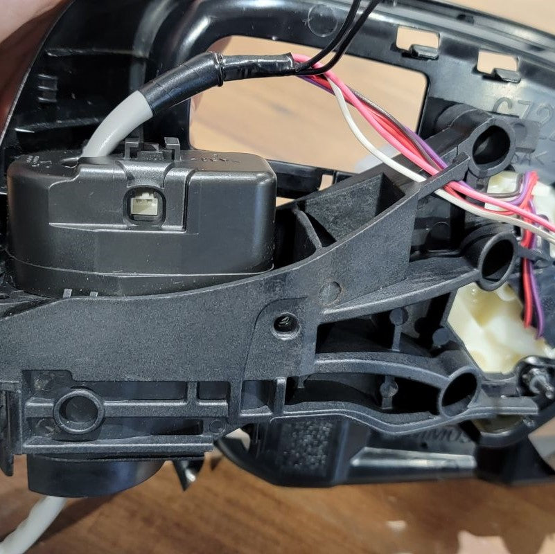
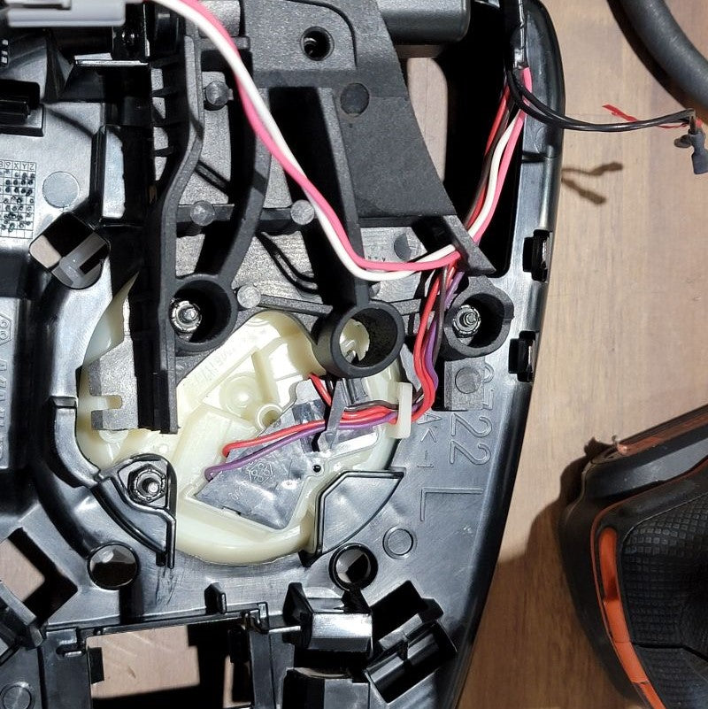
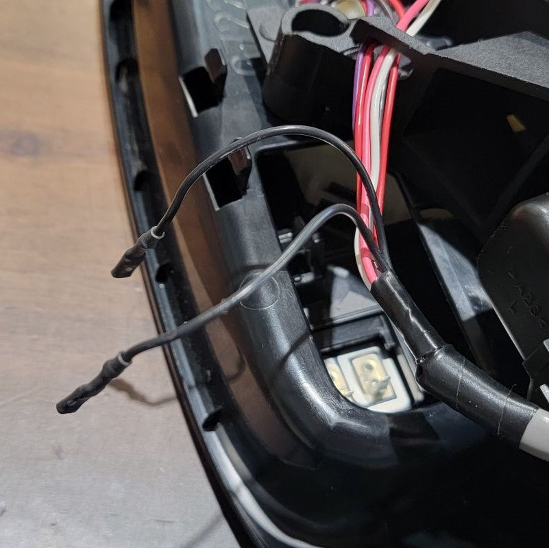
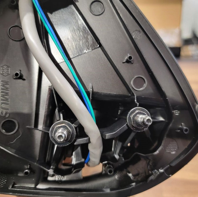
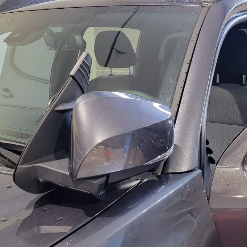
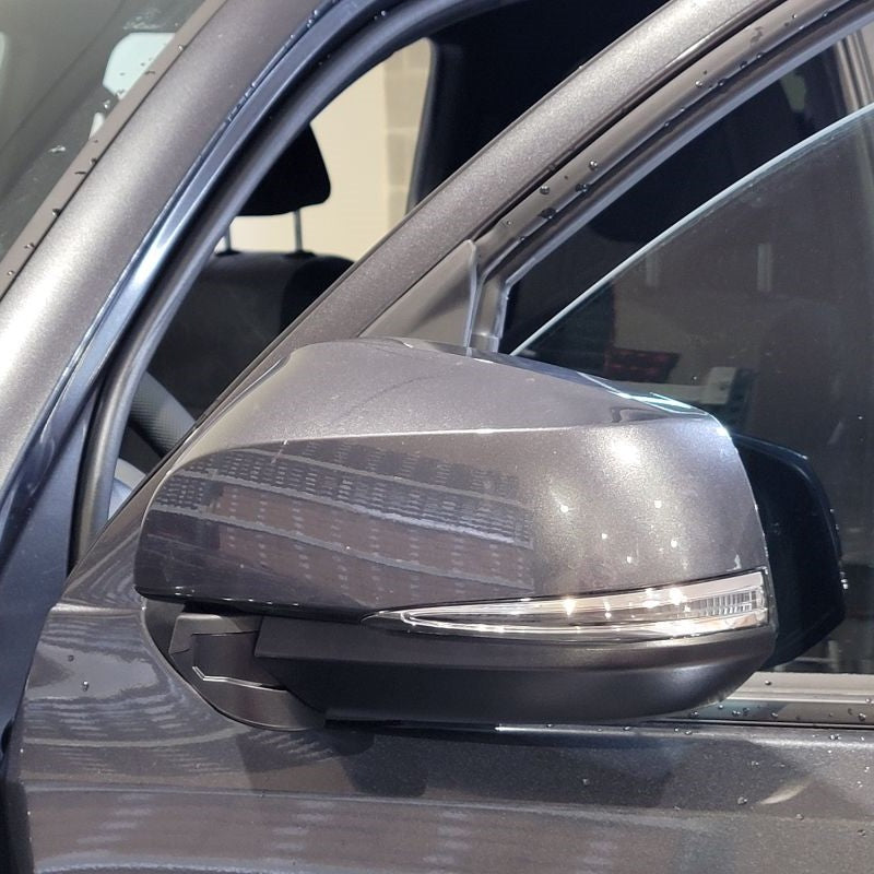
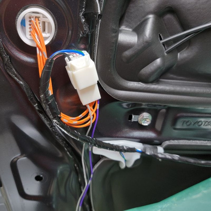
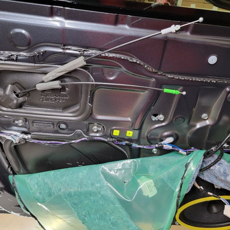
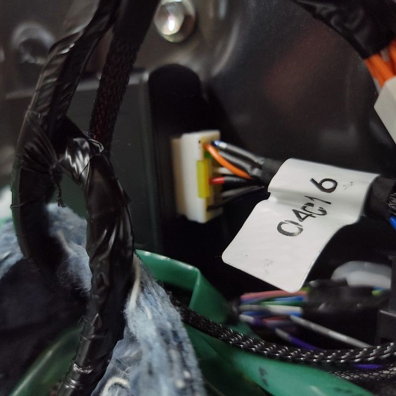
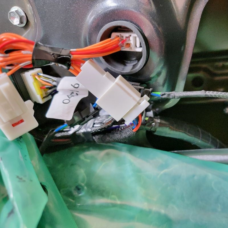
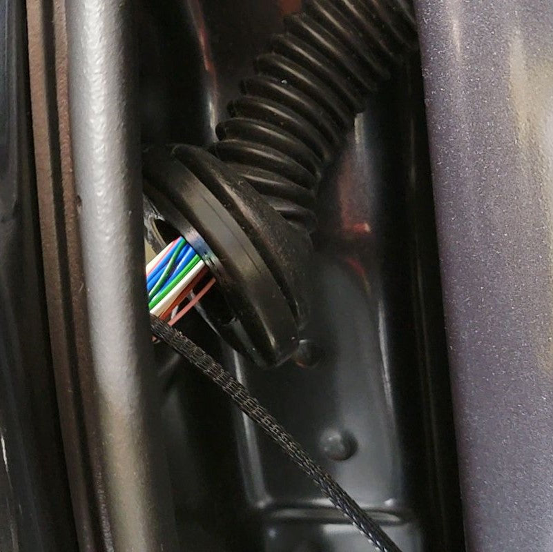
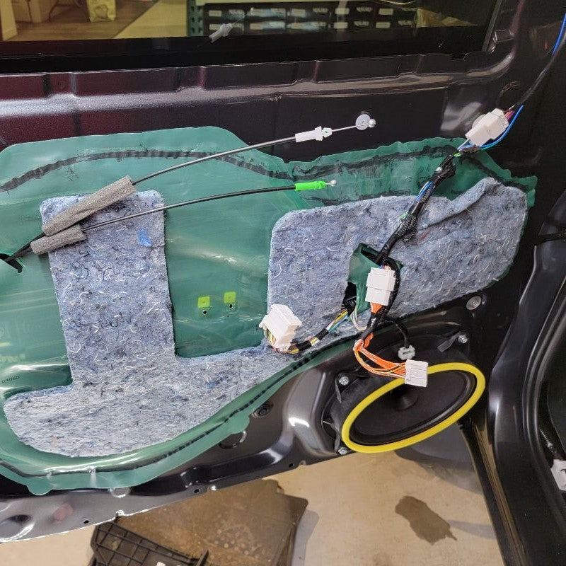
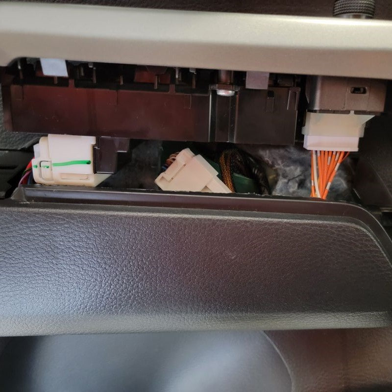
With now having the door frame exposed, we can easily find the mirror connector – just follow the wire that’s coming out of the mirror and routing down to the white connector at the top right side of the door. Remove the connector and any tape holding the cable in place.
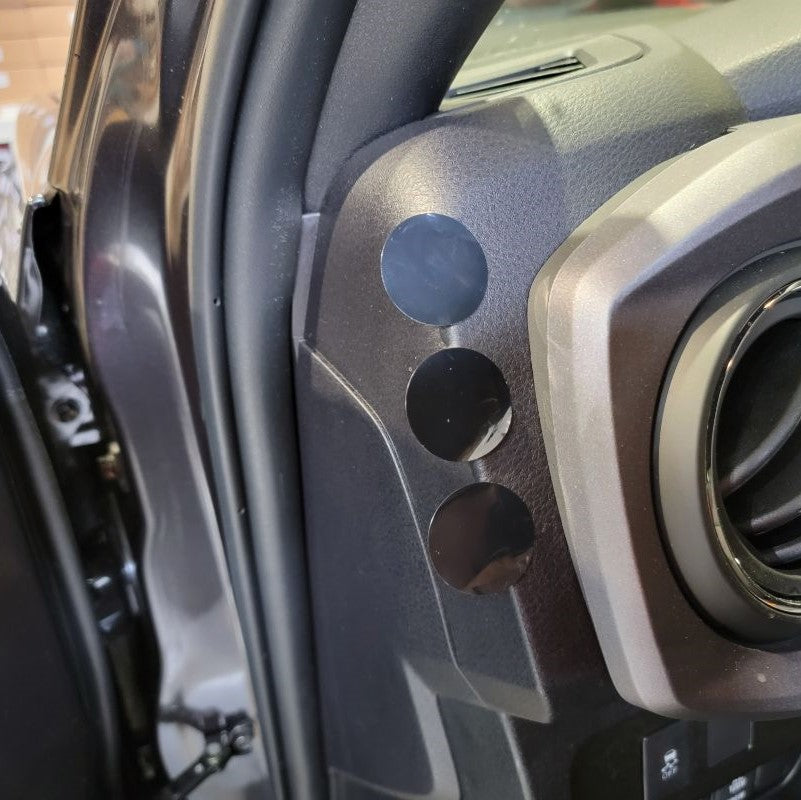
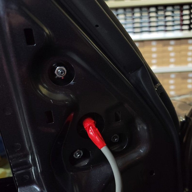
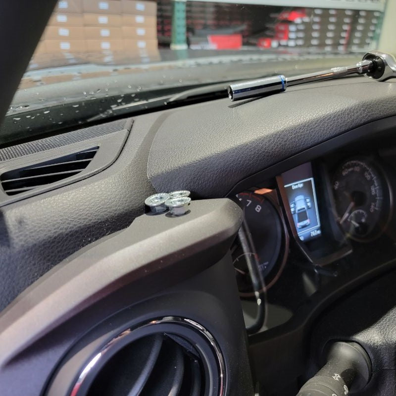
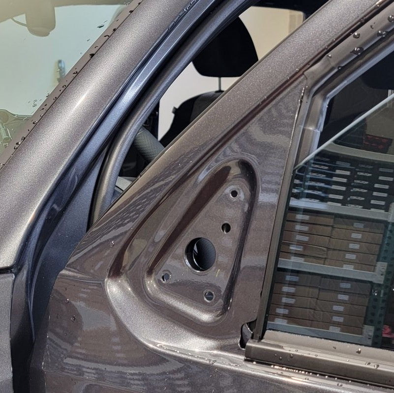
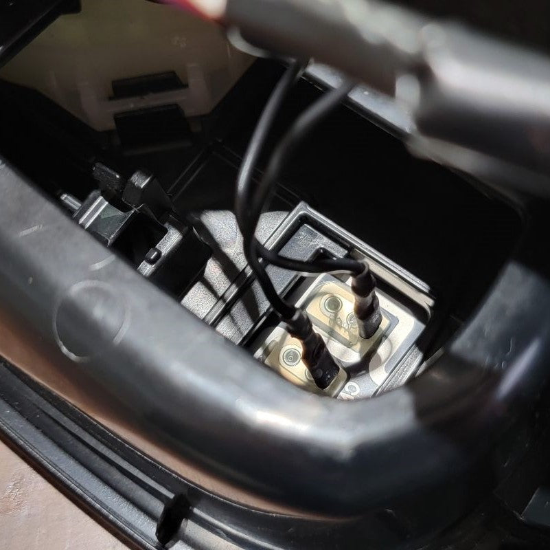
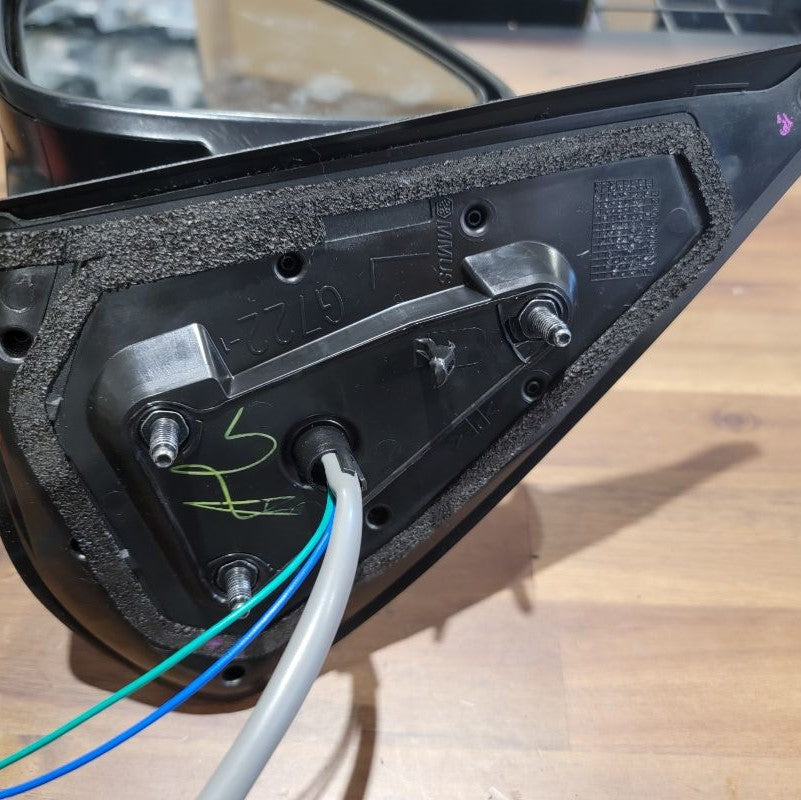
Next, unbolt the mirror assembly by removing the three 10mm nuts that were exposed in Step 1. Carefully push back the plastic tab that’s still holding the mirror in place and pull the whole assembly out, cable and all.
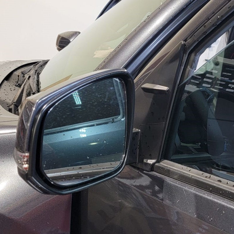
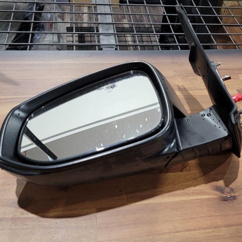
Set the driver side mirror to the side and follow Steps 1-3 for the passenger side mirror as well.
INSTALL IMAGES


STEP 4
-
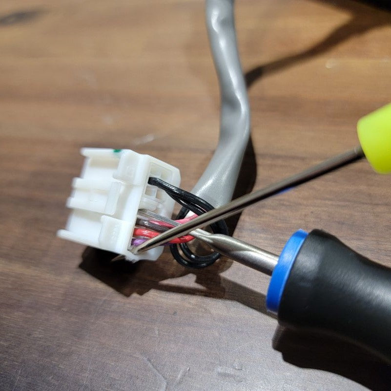
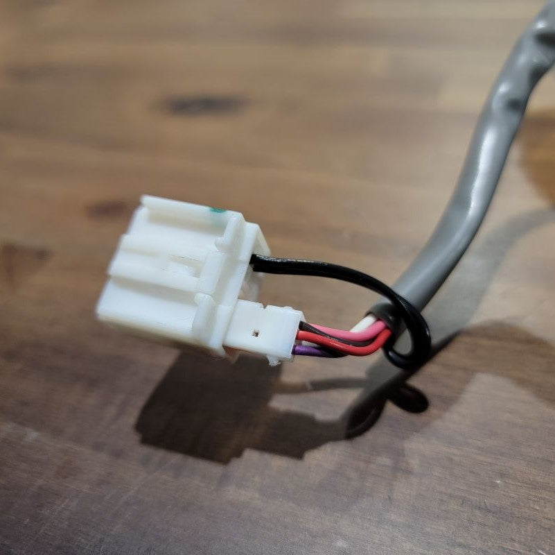
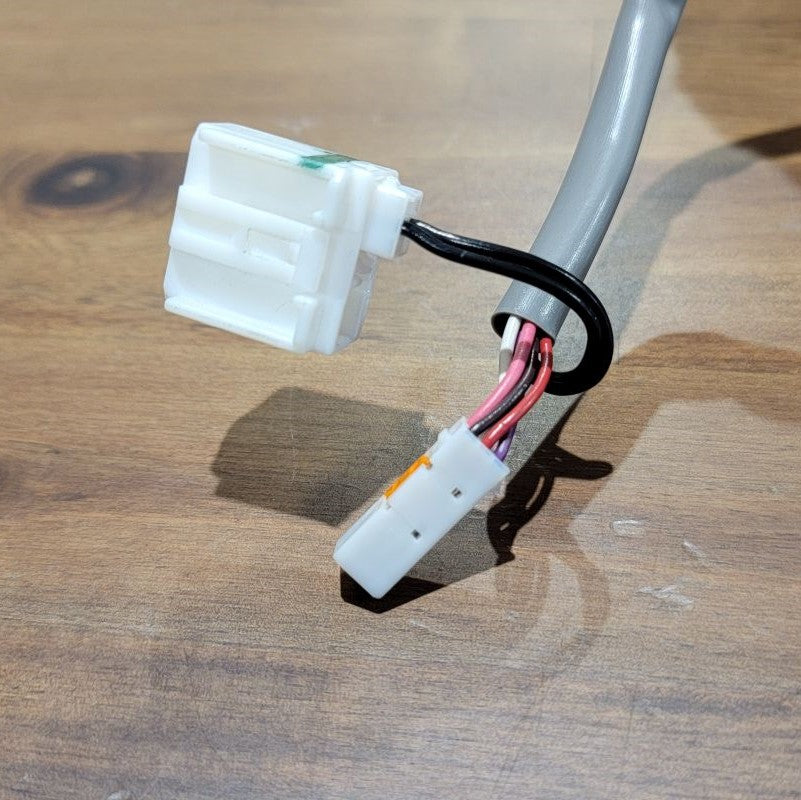
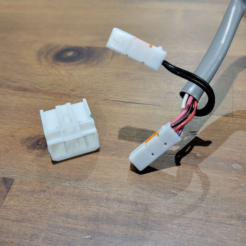
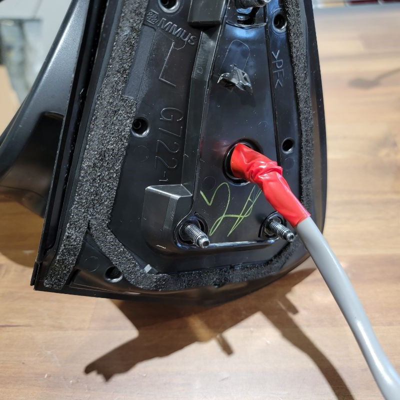
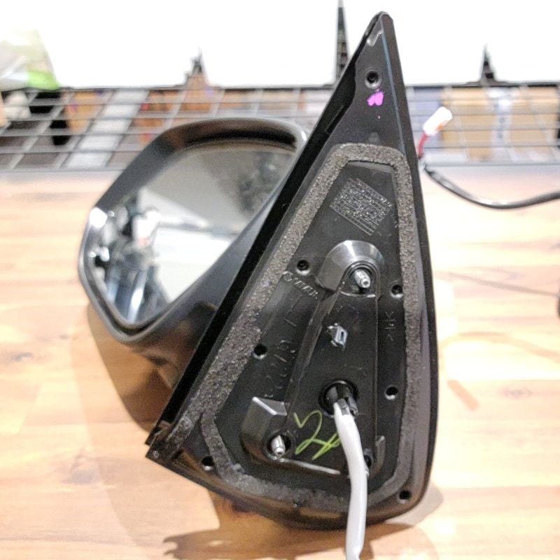
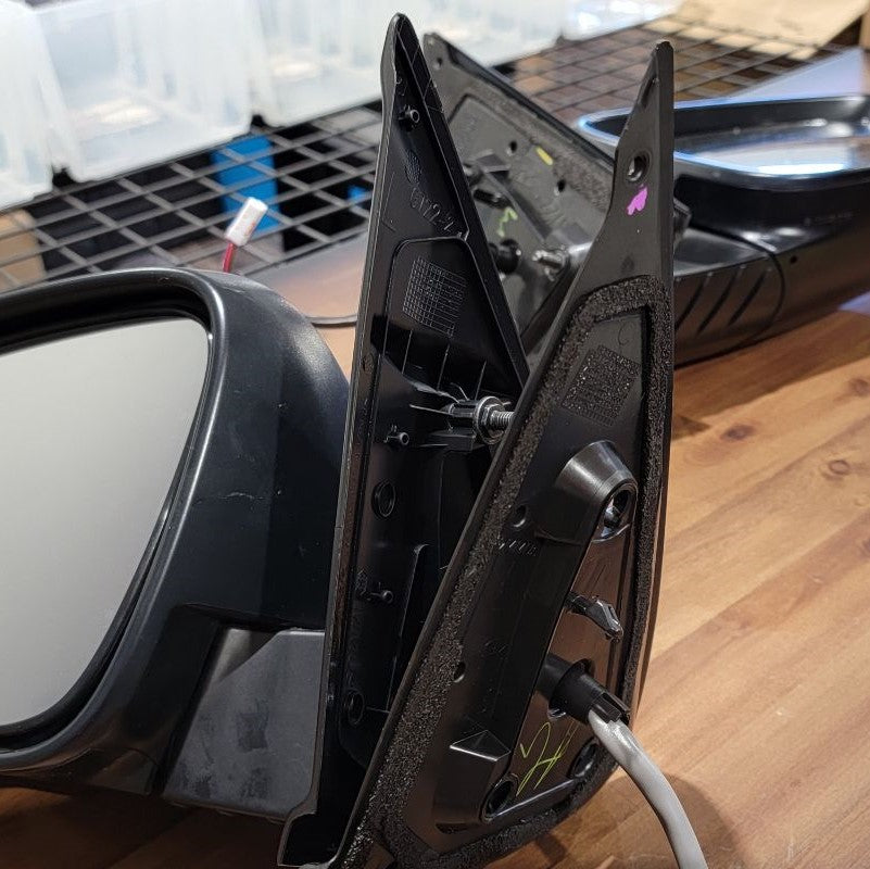
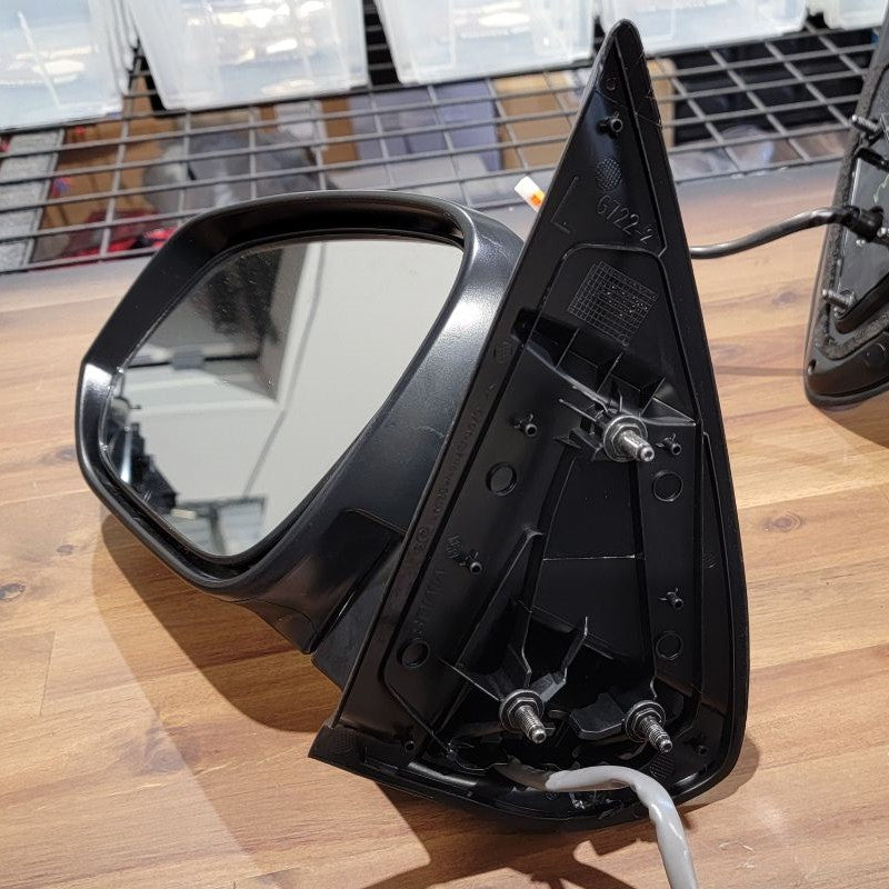
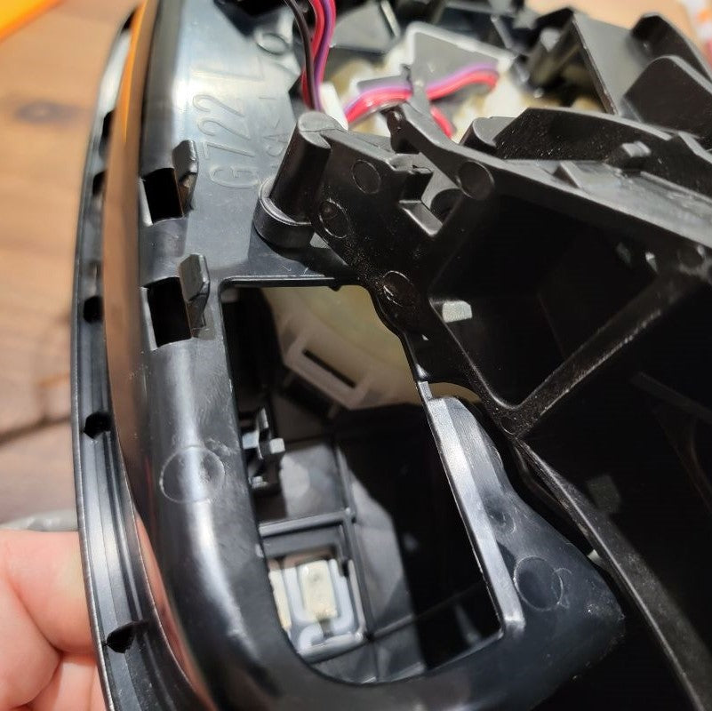
This is a tricky step.
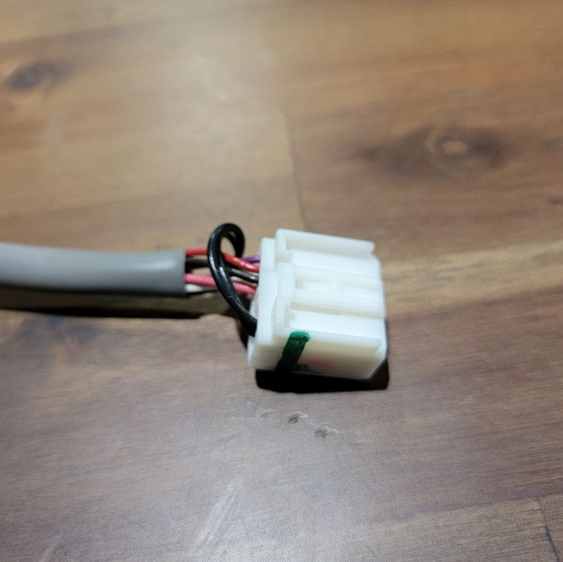
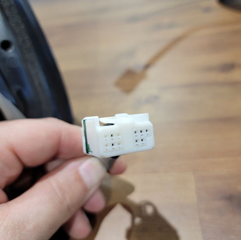
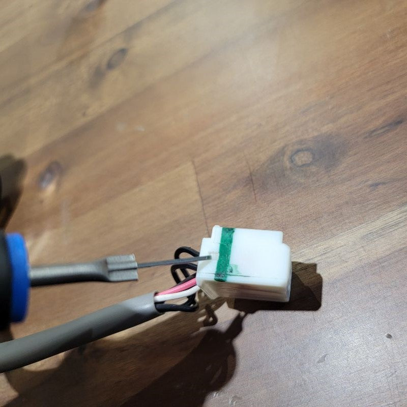
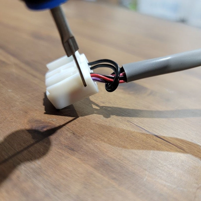
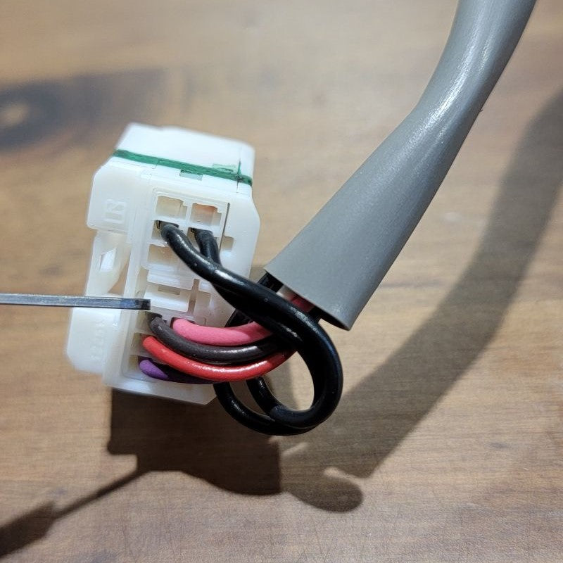
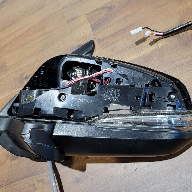
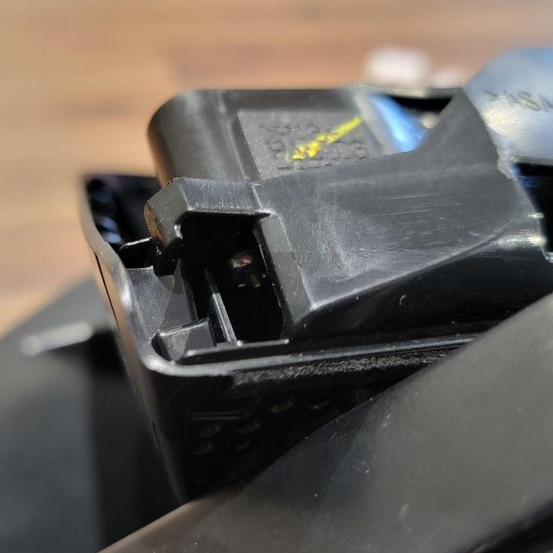
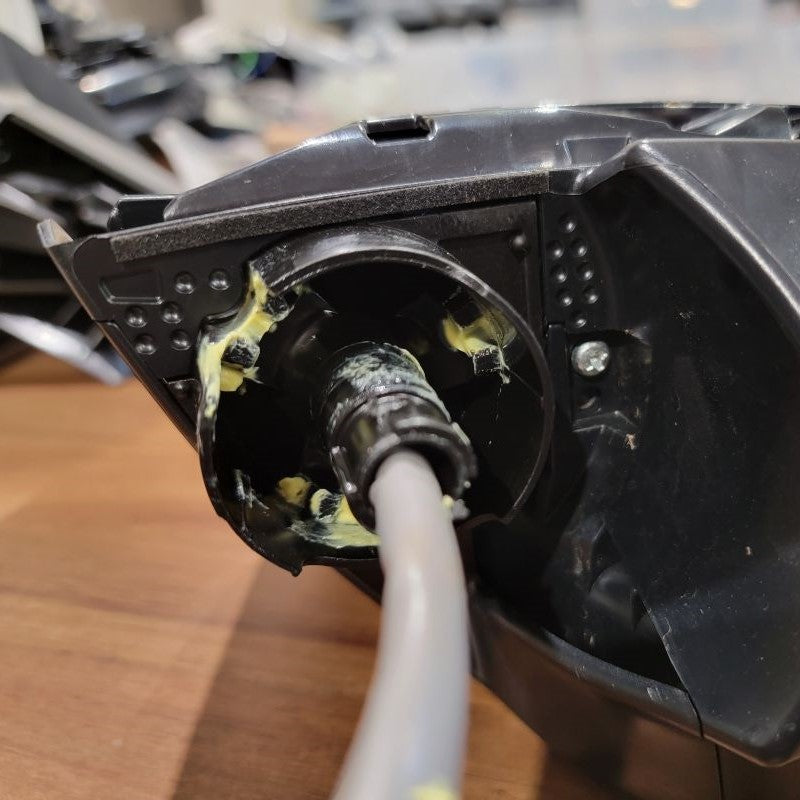
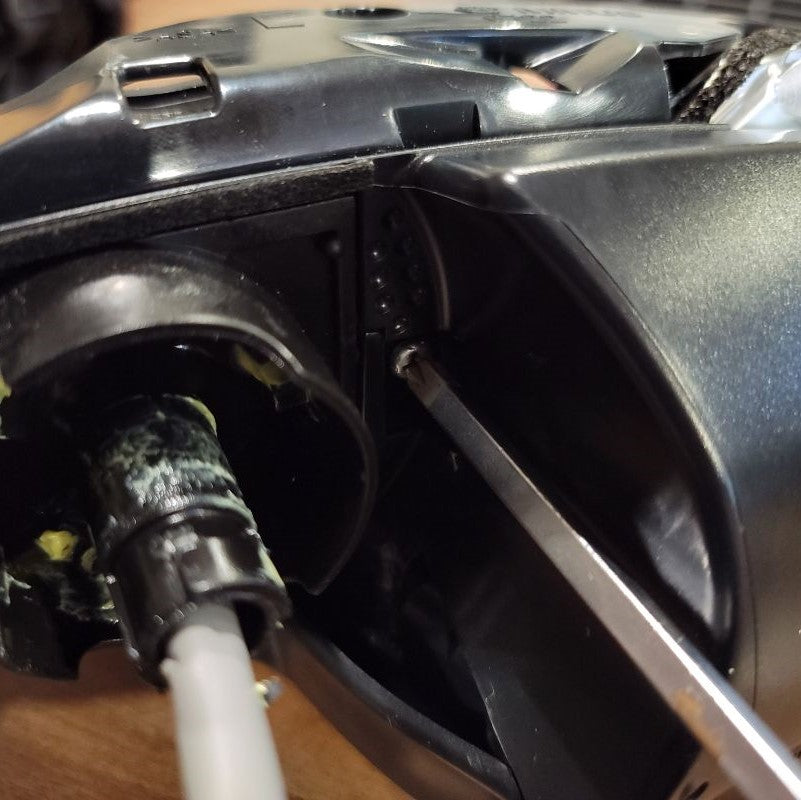
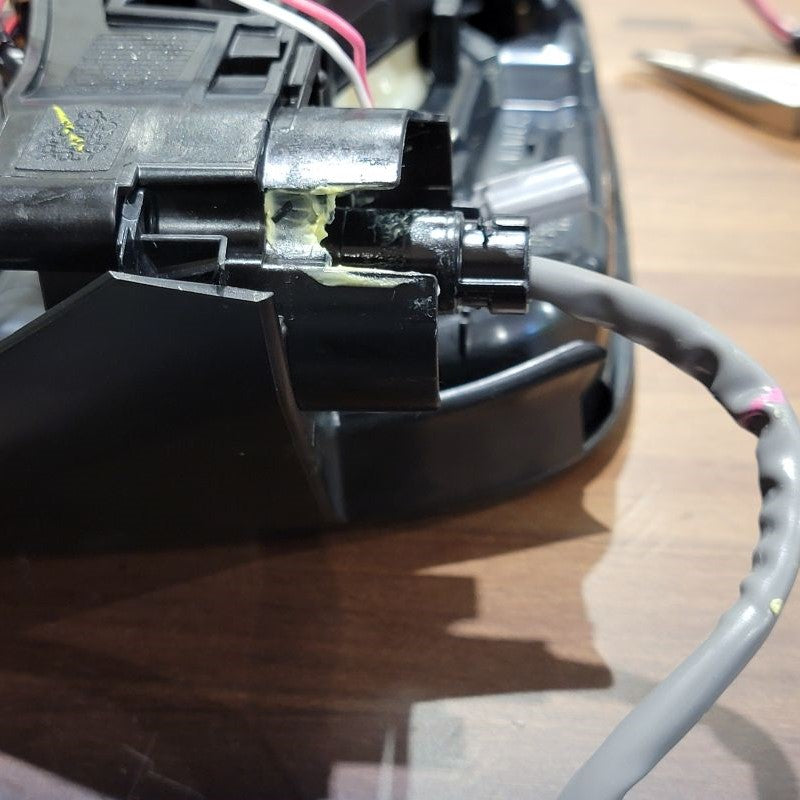
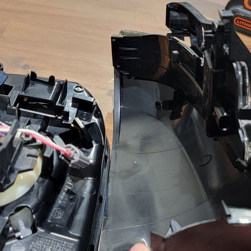
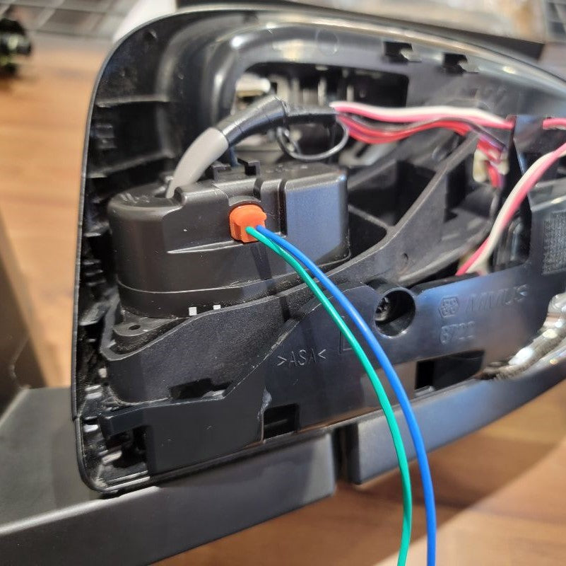
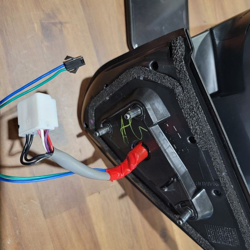
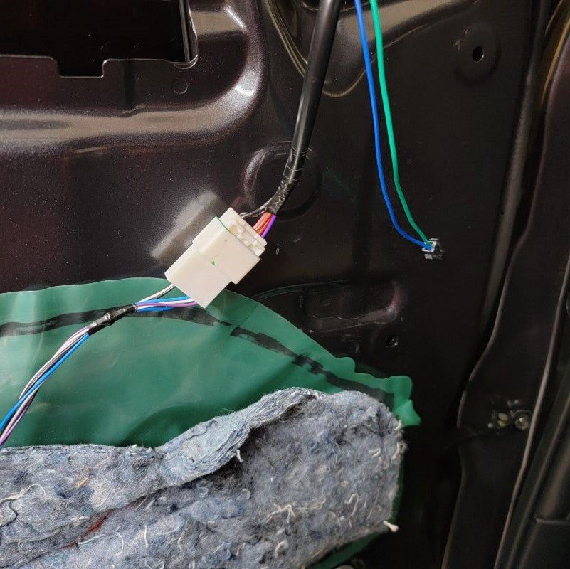
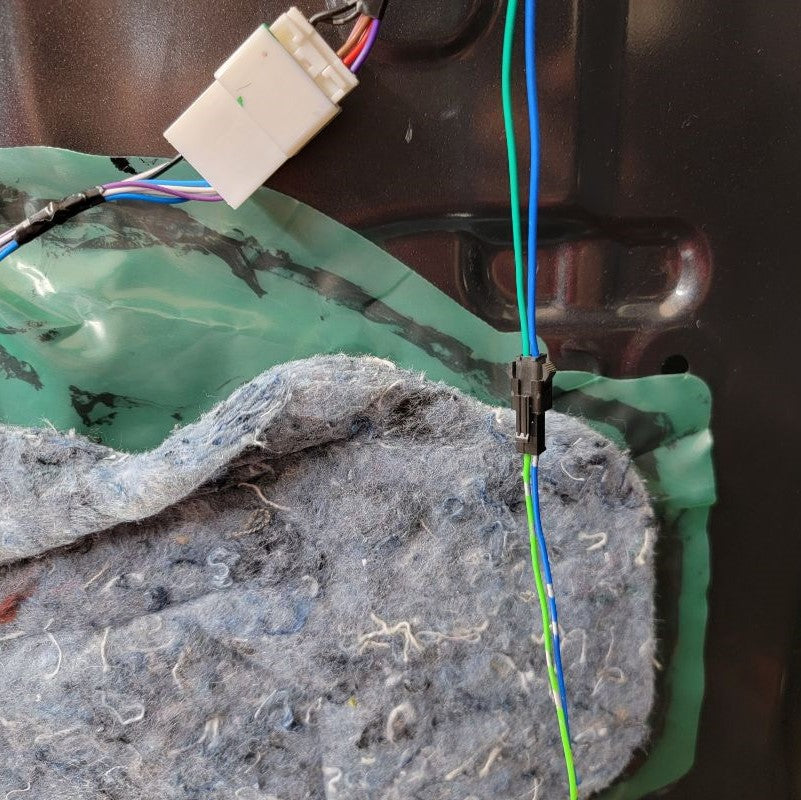
In order to fully disassemble the mirror, there are some narrow openings that the cable and connectors will need to travel through. The only way this can be accomplished is by separating the two small connectors from their outer enclosure. Depending on your year/model truck, your connector may be different. Use the same technique to seperate your mirror connector.
Grab a small flat head screw driver or your tool of choice and look closely at the full connector, you’ll notice four captive barbs on the external sides and between the two internal connectors. These need to be pushed in to release the internal connectors from the outer enclosure. Again, be careful that you do not damage this outer enclosure in the process as it will be needed to reassemble the two smaller connectors towards the end of this mod.
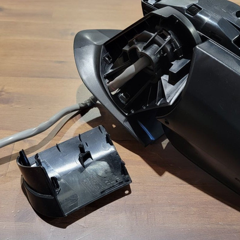
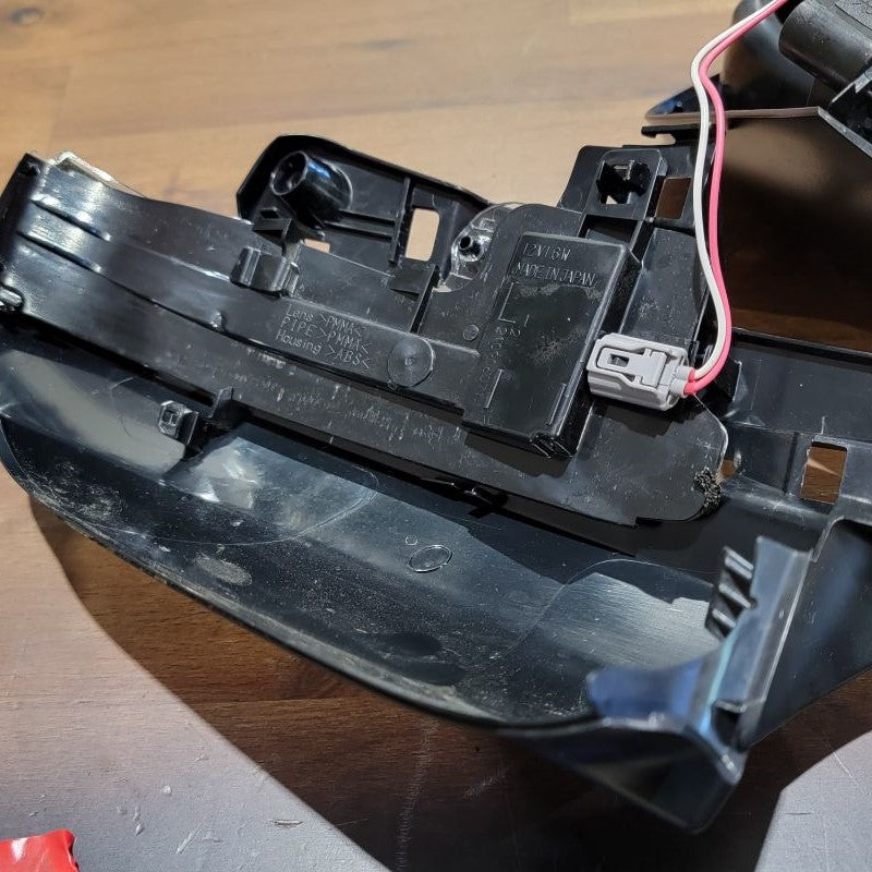
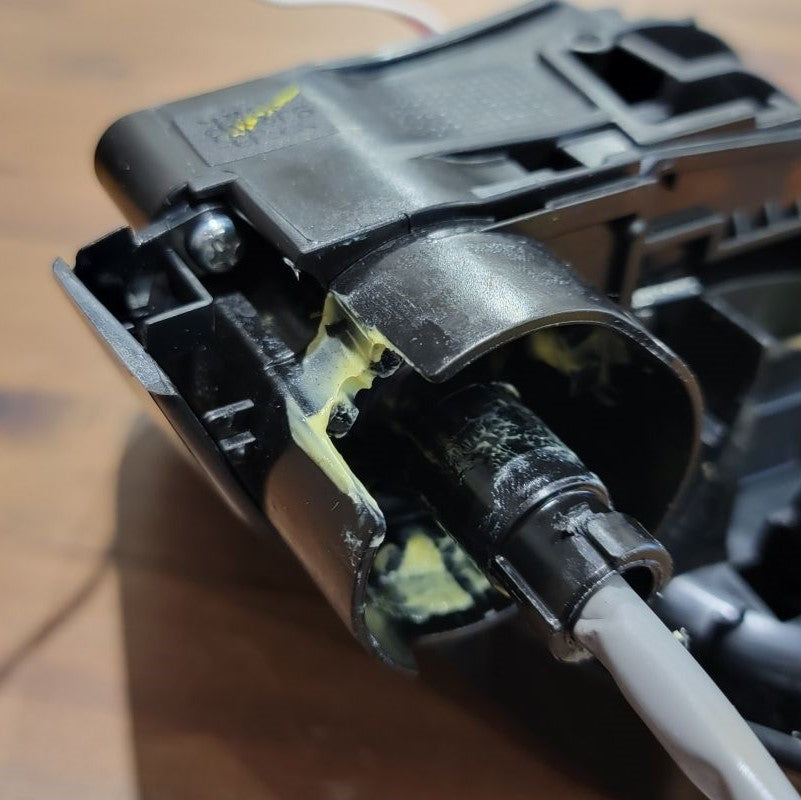
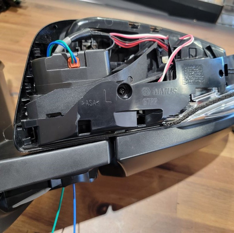
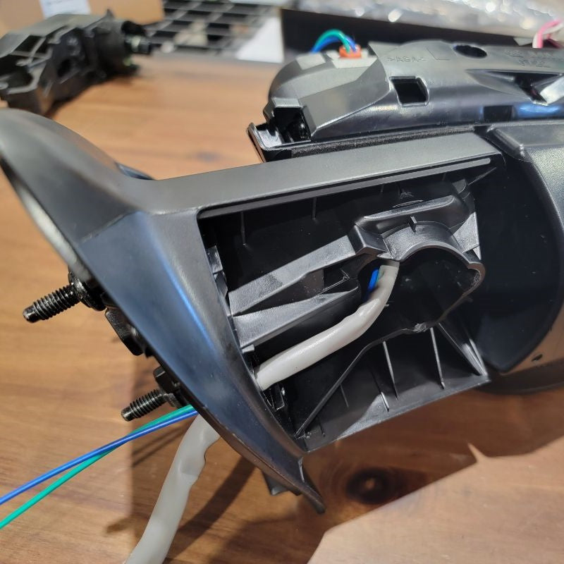
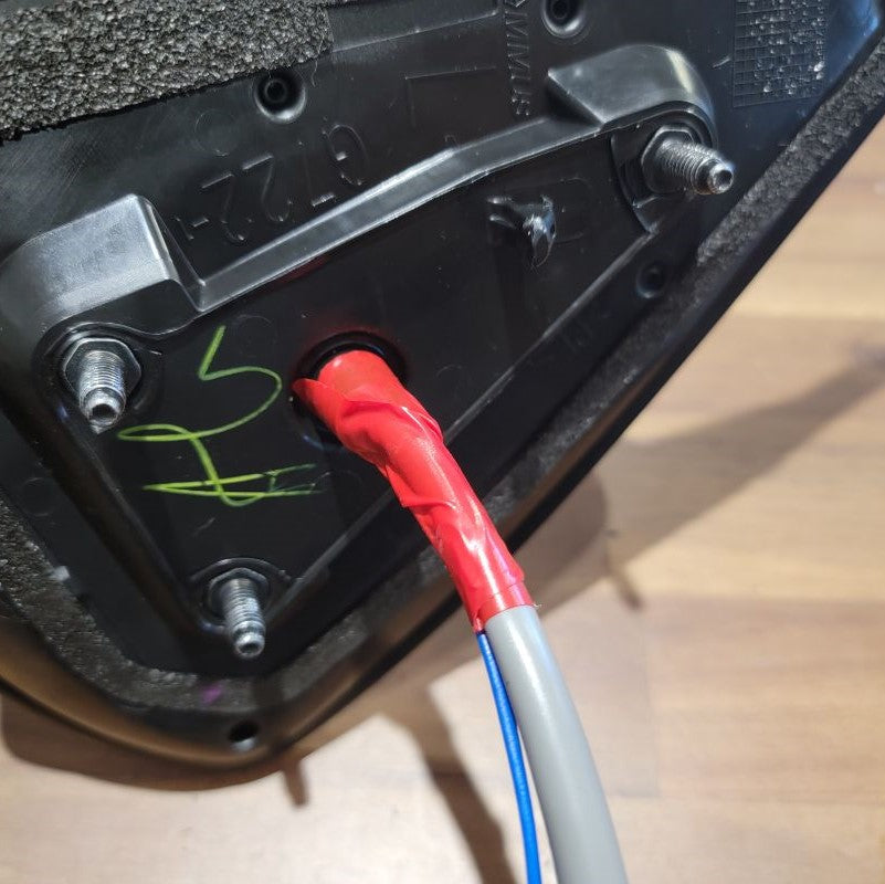
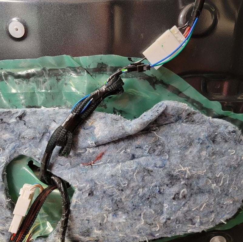
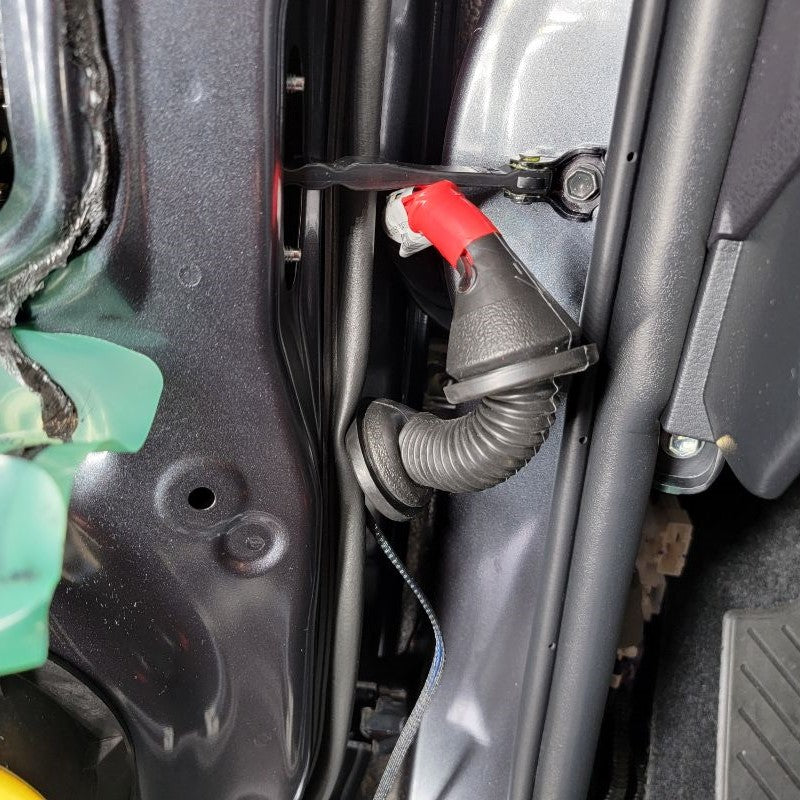
Next, peel off the rubber isolator from the mirror assembly and slip the cable through it. You may have tape that needs to be removed before the rubber isolator is able to be fully removed. Make note of how the mirror cable is routed behind the rubber isolator. Set this aside for the end.
INSTALL IMAGES


STEP 5
-
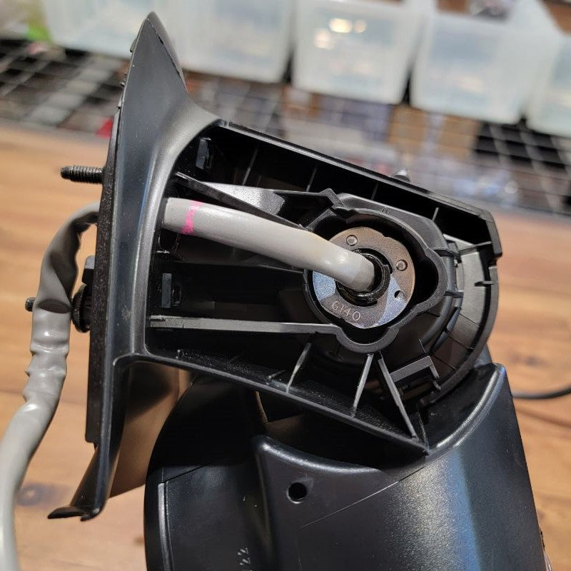
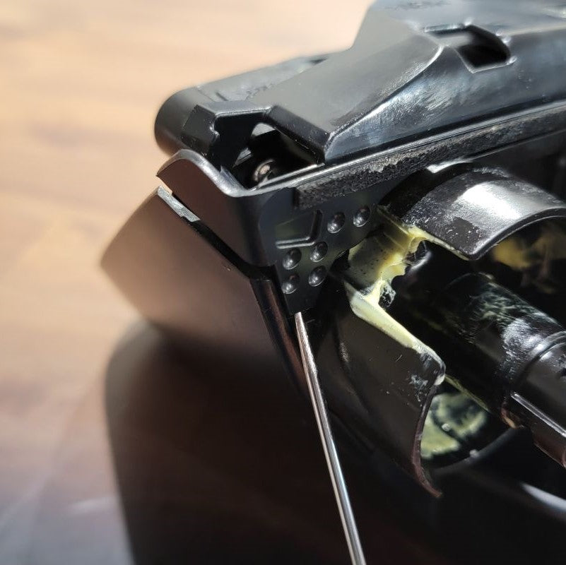
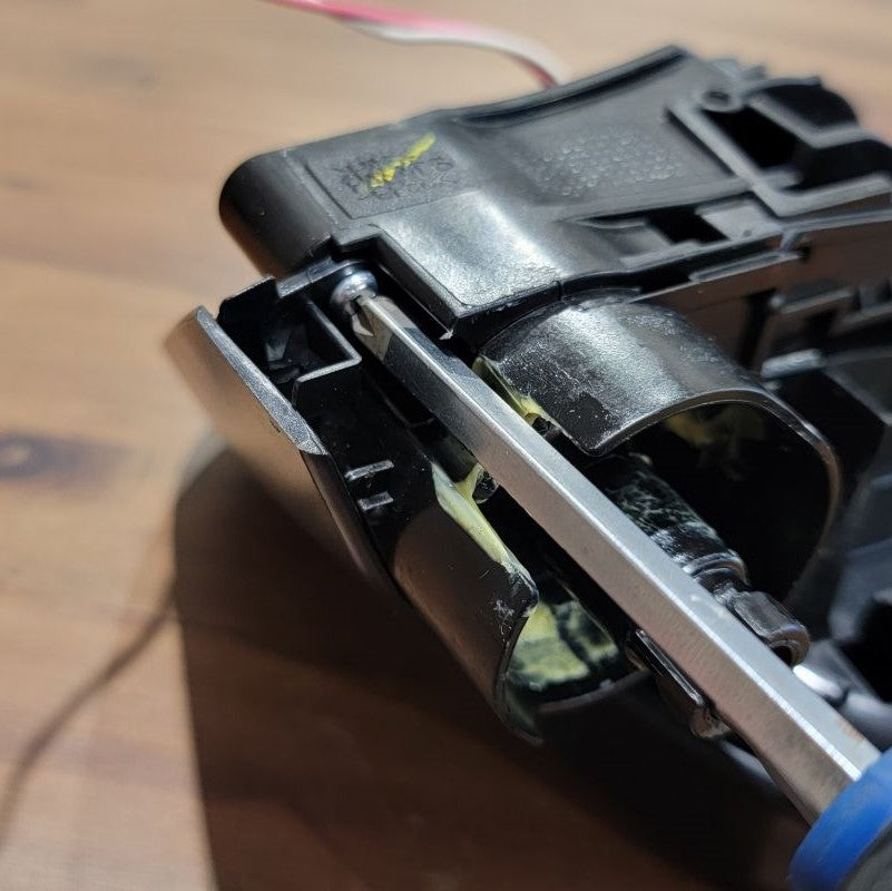
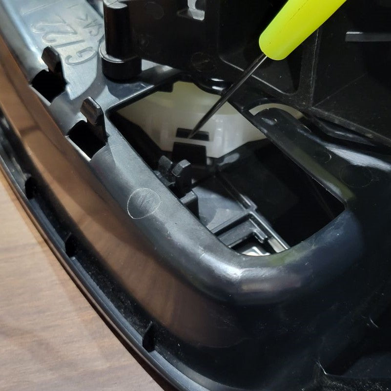
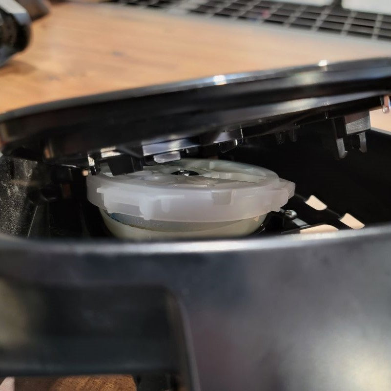
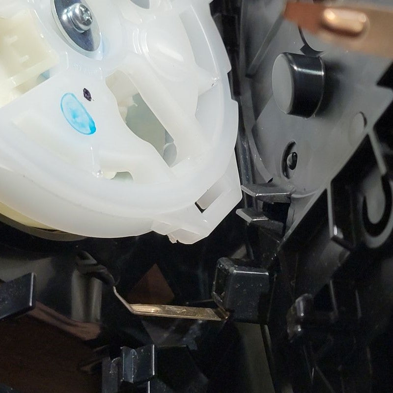
Using the trim removal tool, carefully pry open the lower mirror arm cover. It’s a handful of snap fits, so be careful not to break any.
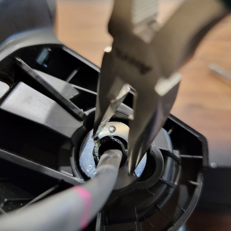
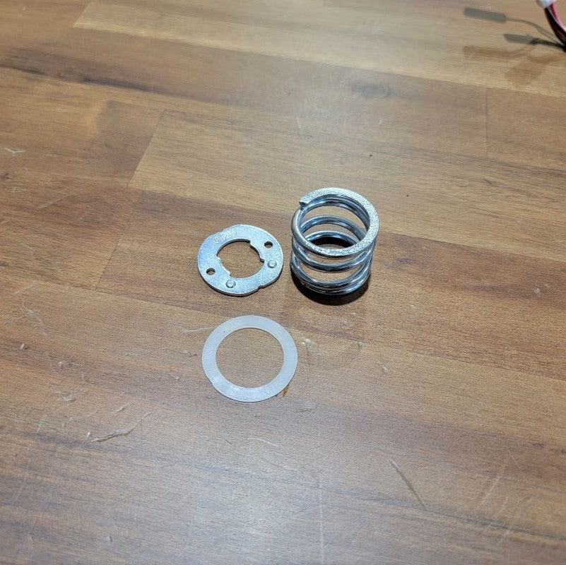
Bring out your needle nose pliers for this step. The metal clip here is keeping the mirror spring-loaded in open and closed detents.
With the addition of the motor, this becomes unnecessary, so we can get rid of it. Insert the tips of the needle-nose pliers into the two opposing holes on the spring clip.
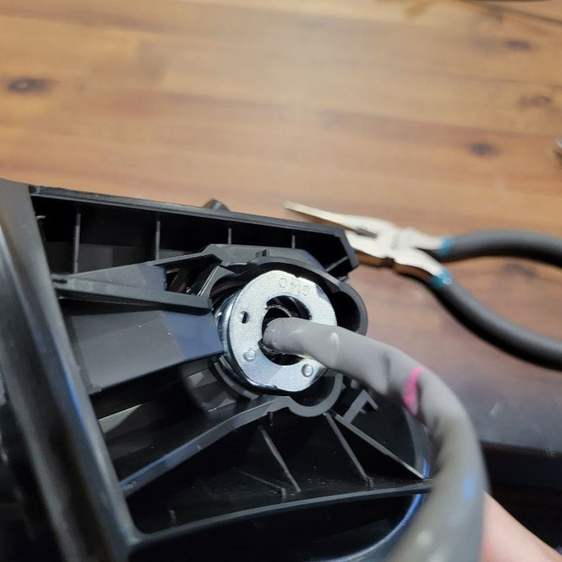
Keeping some force on the pliers to keep the tips inserted, give the whole thing a firm twist. This should align the slots on the spring clip with tabs on the center shaft and it should pop right off.
At this point, you can also remove the spring and plastic washer that was being held down by the spring clip.
INSTALL IMAGES


STEP 6
-
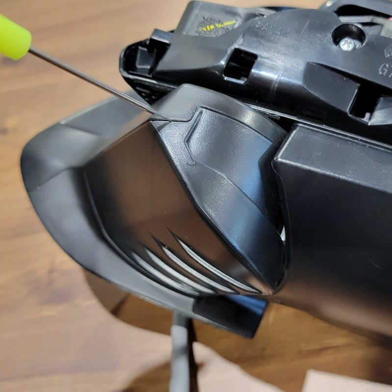
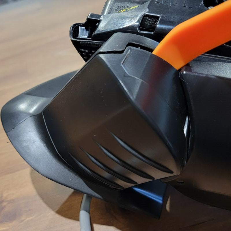
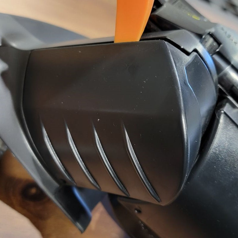
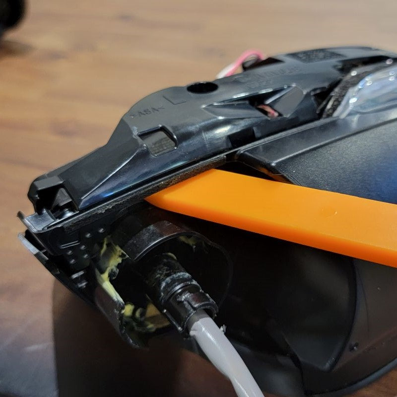
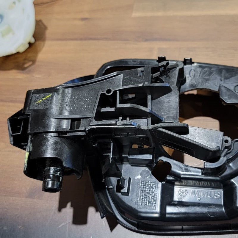
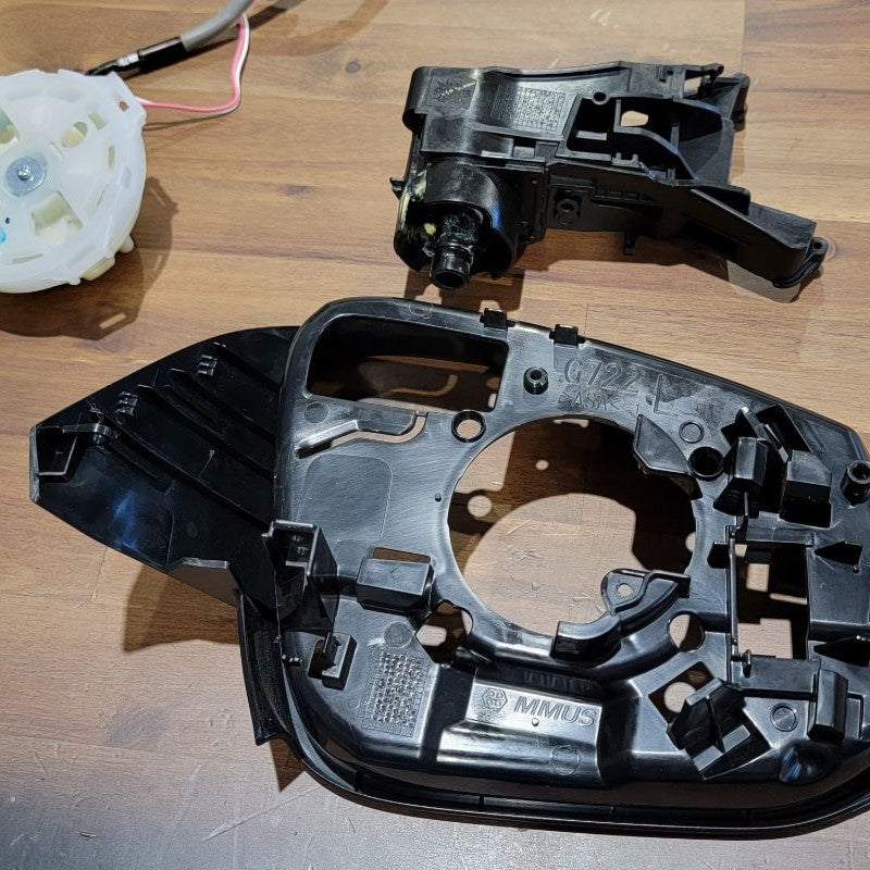
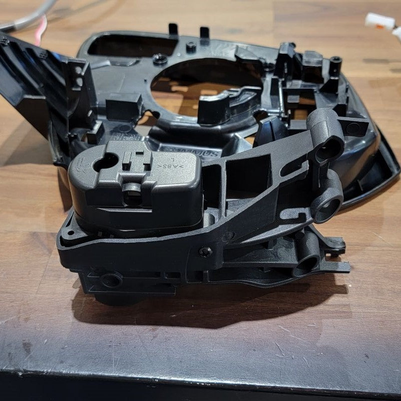
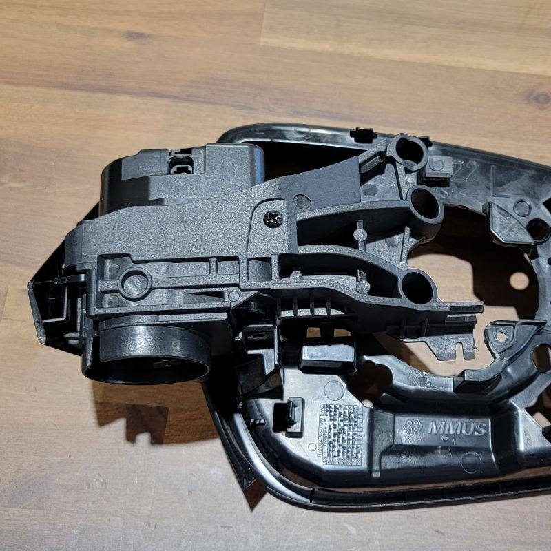
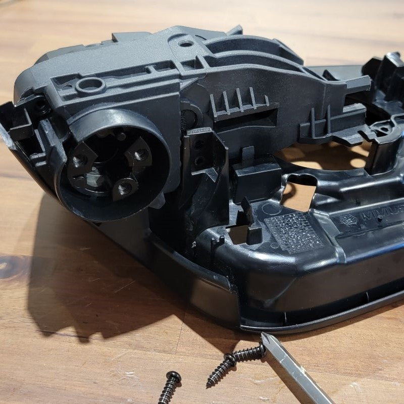
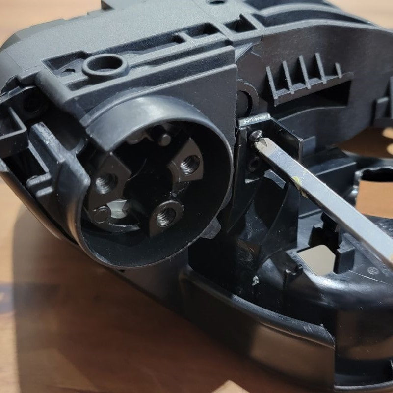
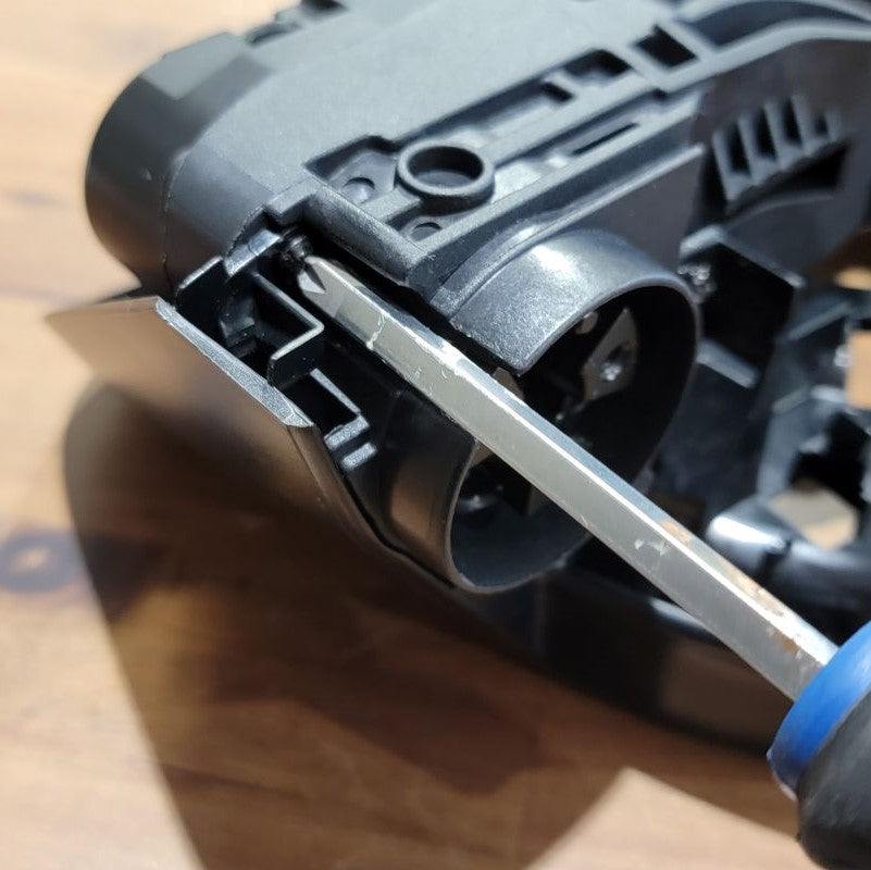
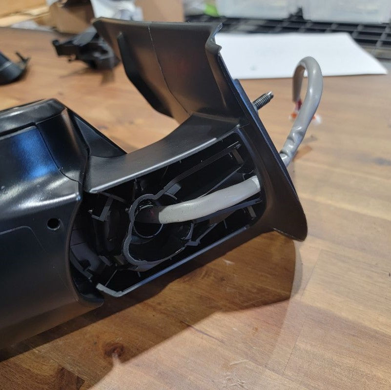
In order to remove the cosmetic cover, don't be afraid to use your trim removal tool and wedge it in between the mirror housing and the back cover to pry up and pop it off.
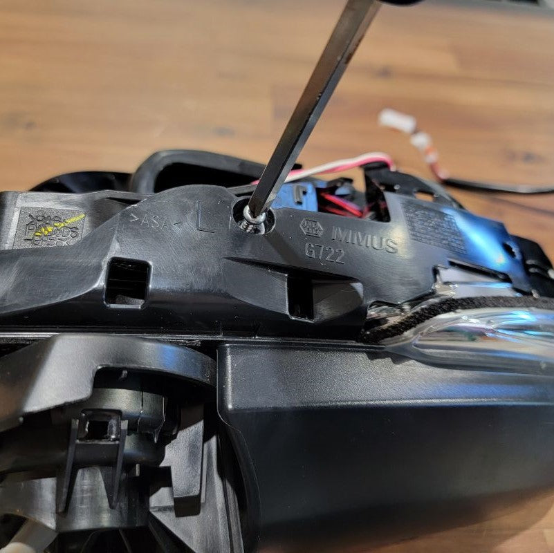
Once the costmetic back cover has been removed, you will now see some screws that need to be removed in order to seperate the lower cover with the turn signal from the mirror housing.
INSTALL IMAGES


STEP 7
-
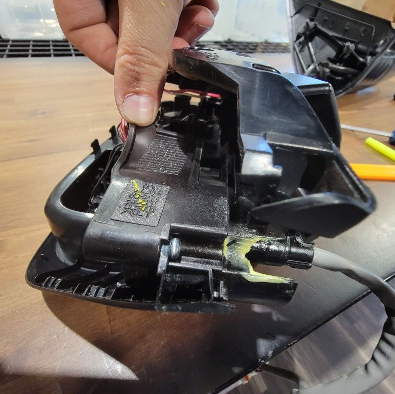
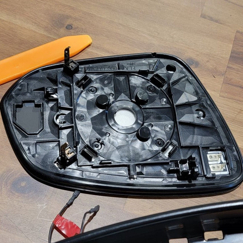
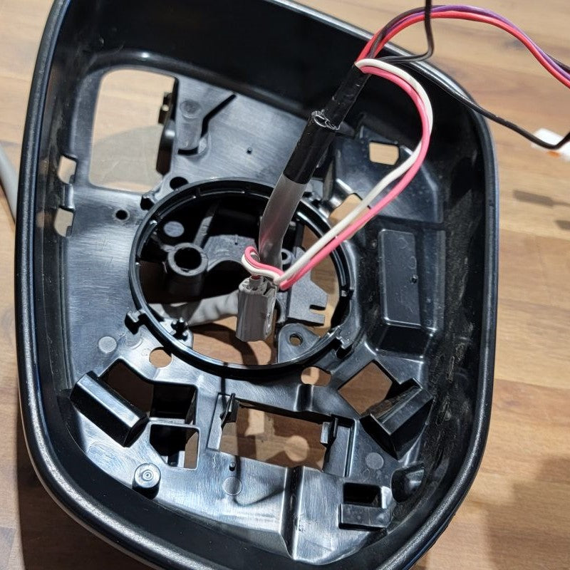
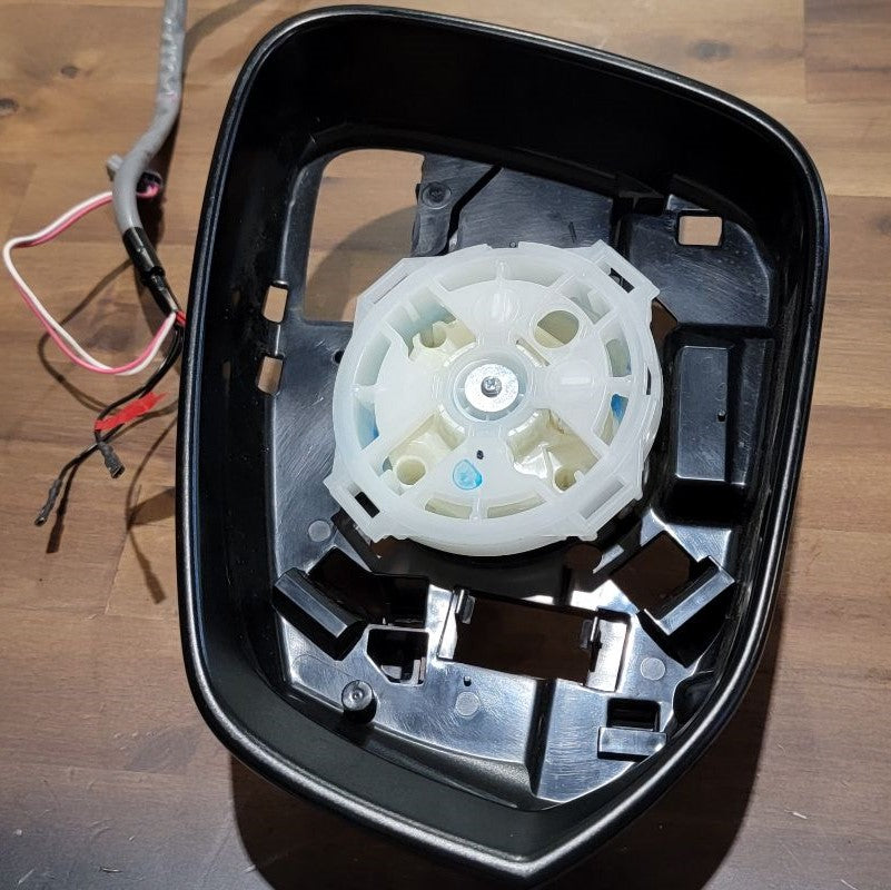
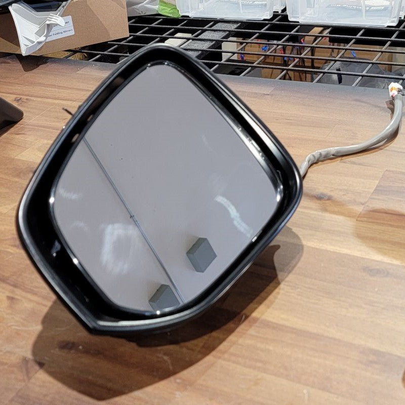
Using the trim removal tool, gently lift the mirror plate out of the housing. It may feel like you’re about to break something, but the mirror plate should pop right out if you continue pulling up.
Before you fully remove it, disconnect the two-pin connector for the mirror defroster.
There’s no latch for this connector, so it may take some force to pull it off due to the snug fit.
Looking at the assembly from the mirror side again, locate these two clips behind the signal light.
Pull each one out and away from the inner bracket to release the light module.
INSTALL IMAGES


STEP 8
-
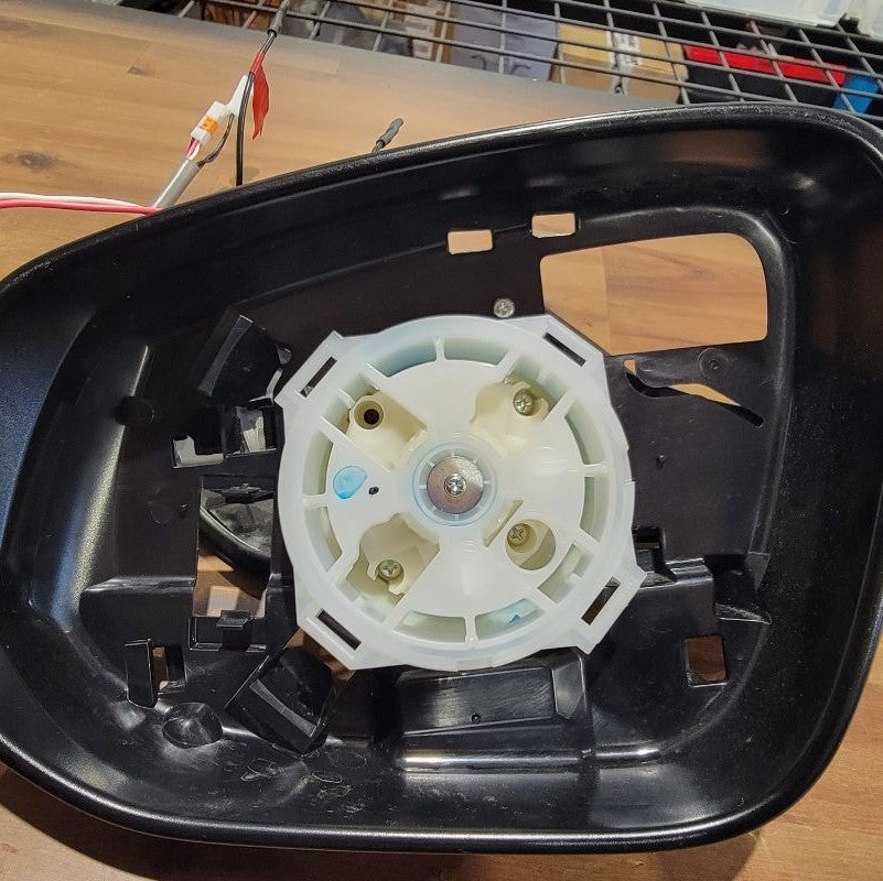
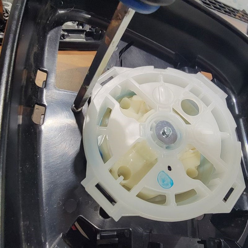
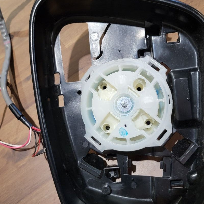
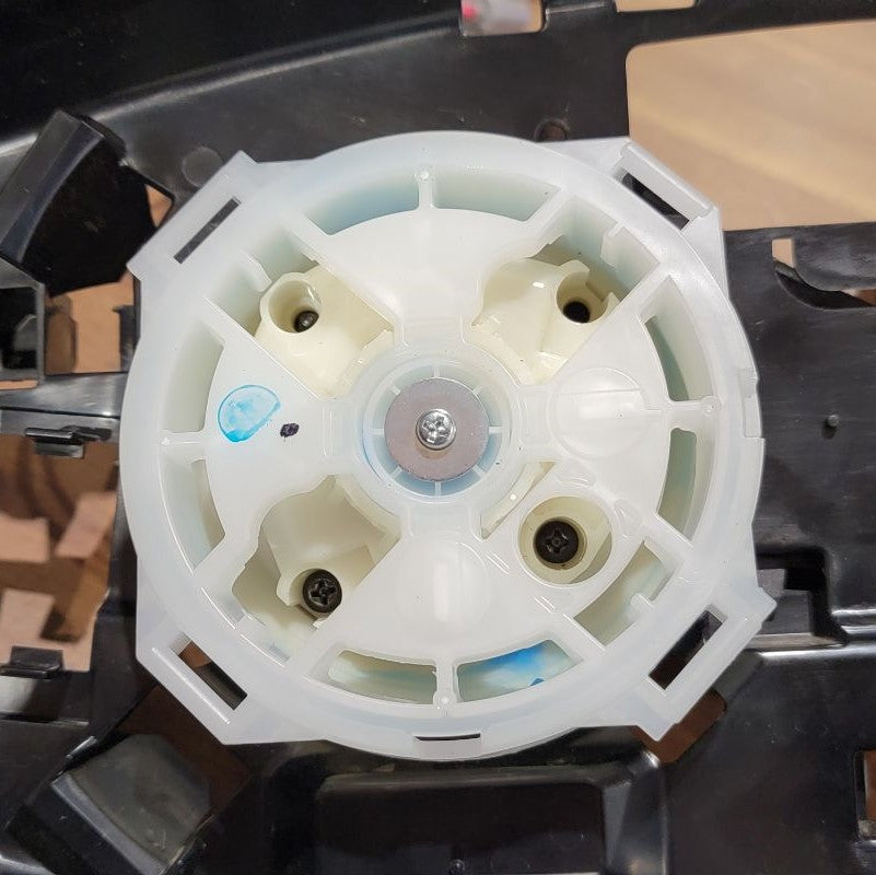
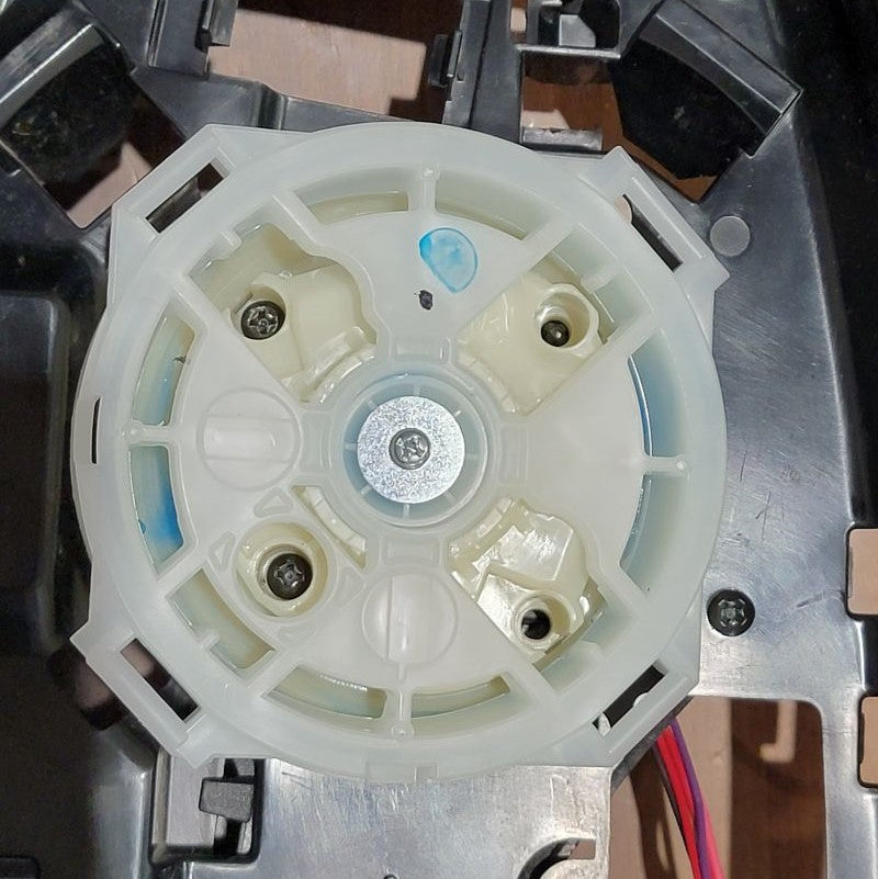
Remove these five screws holding the arm bracket in place, and remove the bracket. The kit that we’re installing comes with replacement arm connection brackets with integrated motor and gearbox that we’ll swap in.
Before assembling the new bracket, you can disgard the old arm connection bracket, spring, and washers as they’re unnecessary for our actual assembly.
We'll be reusing some of the original mirror assembly screws that we removed in Step 7.
Now we can swap in the new arm bracket. The fit should be almost identical to the original arm bracket, so follow what you did in Step 7, except backward.
Use the new 6 screws with locknuts to assemble the actuator to the new arm bracket using all the previous screw locations you removed. However, on the backside, use the provided locknuts to secure.
INSTALL IMAGES


STEP 9
-
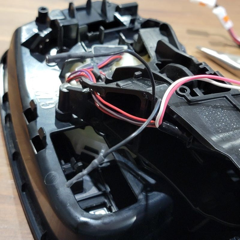
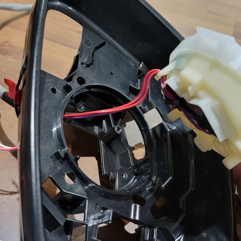
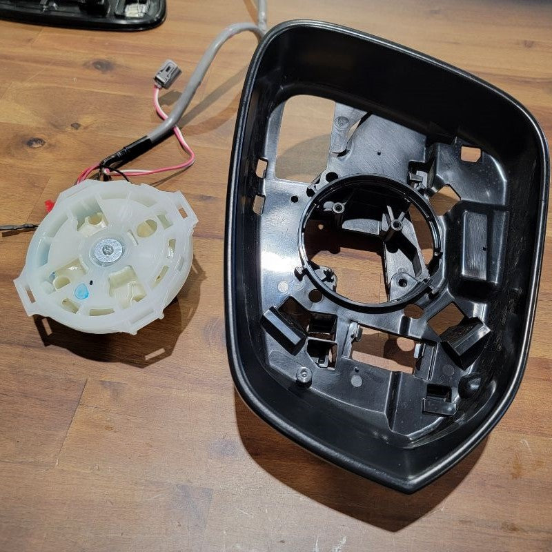
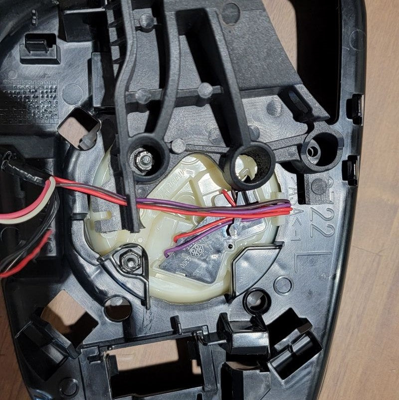
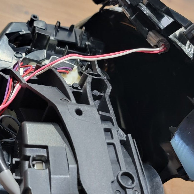
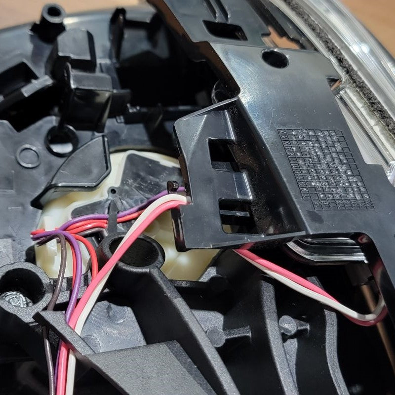
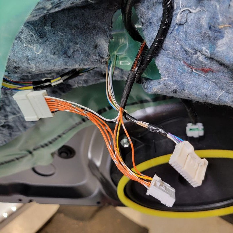
Next, tidy the wires up (including the two new wires from the motor) and route them back through the hole in the new arm bracket.
Both outer covers can be assembled at this time – just follow the steps you took previously, except backward.
Go ahead and re-assemble your mirror assembly by starting with your mirror and lining up notches on the back of the glass. Run the wire harness through all their tabs and down the new motor center slot.
Note: Make sure you do not forget to plug the turn signal connector back together before you reconnect the bottom cover.
INSTALL IMAGES


STEP 10
-
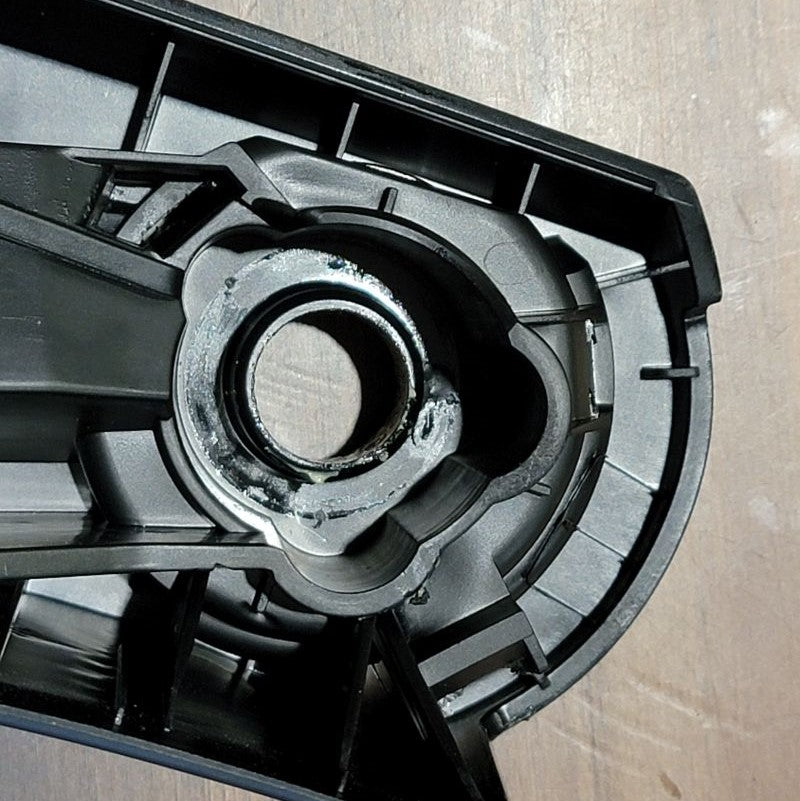
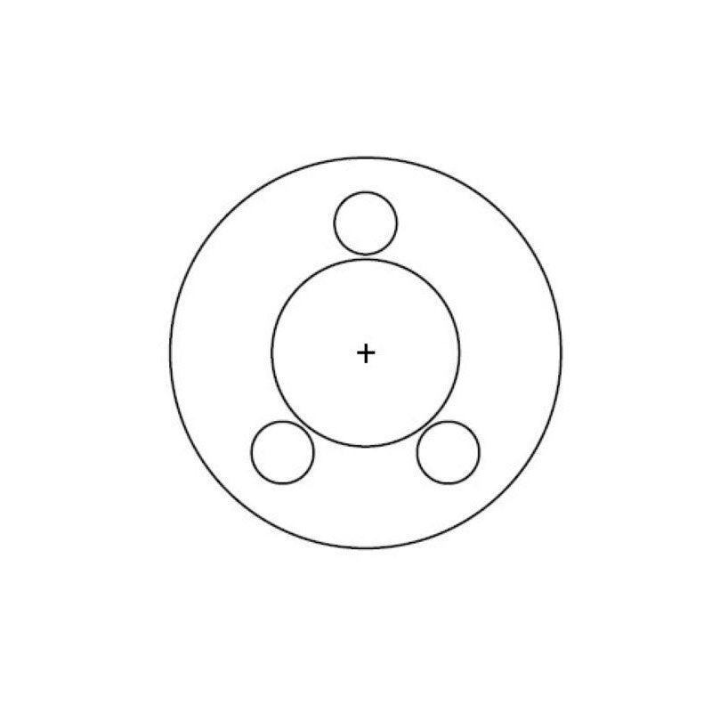
This is another time consuming step. Toyota did not do us Tacoma Owners a favor here by providing us three factory holes in our factory mirror arms to our mirrors. Therefore, we need to drills three holes just like the diagrams shows below to match the motor that we will be installing into our mirrors. Luckily, we have three indentions in our hinges that you will see when looking at your own oem mirrors to go off of as to where these three holes should go as a guide. Again, by taking on this DIY kit, you must be willing to drill into your own factory hinges at your own risk.
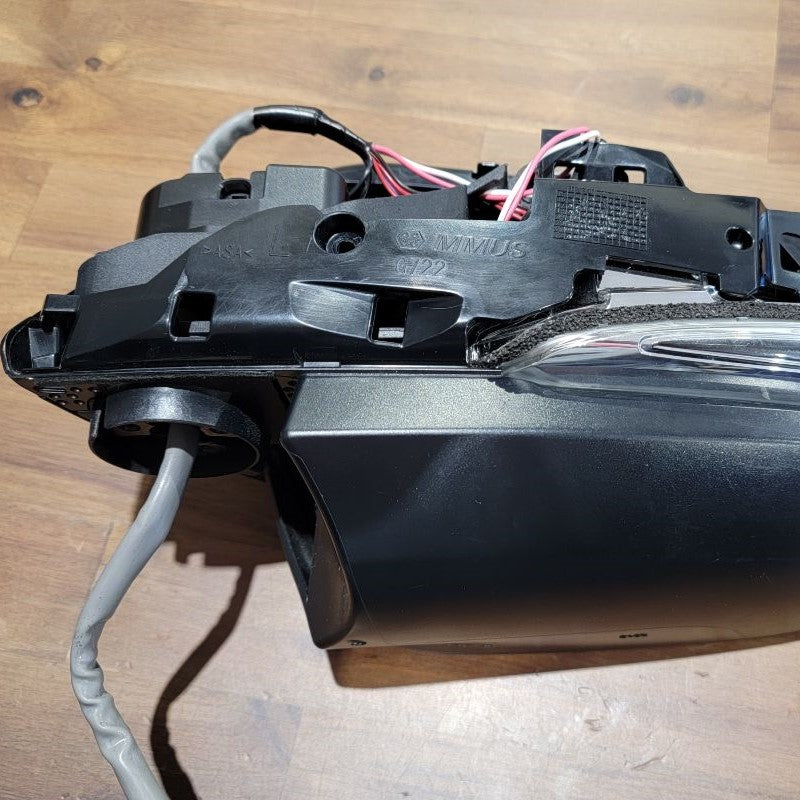
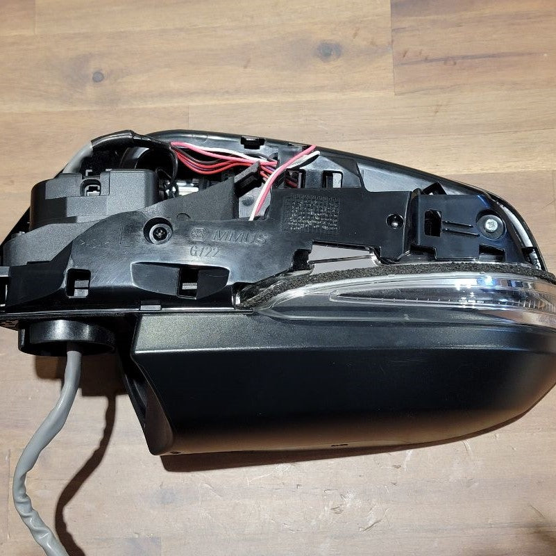
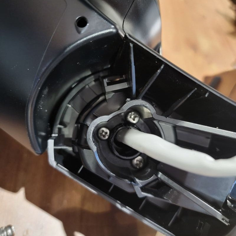
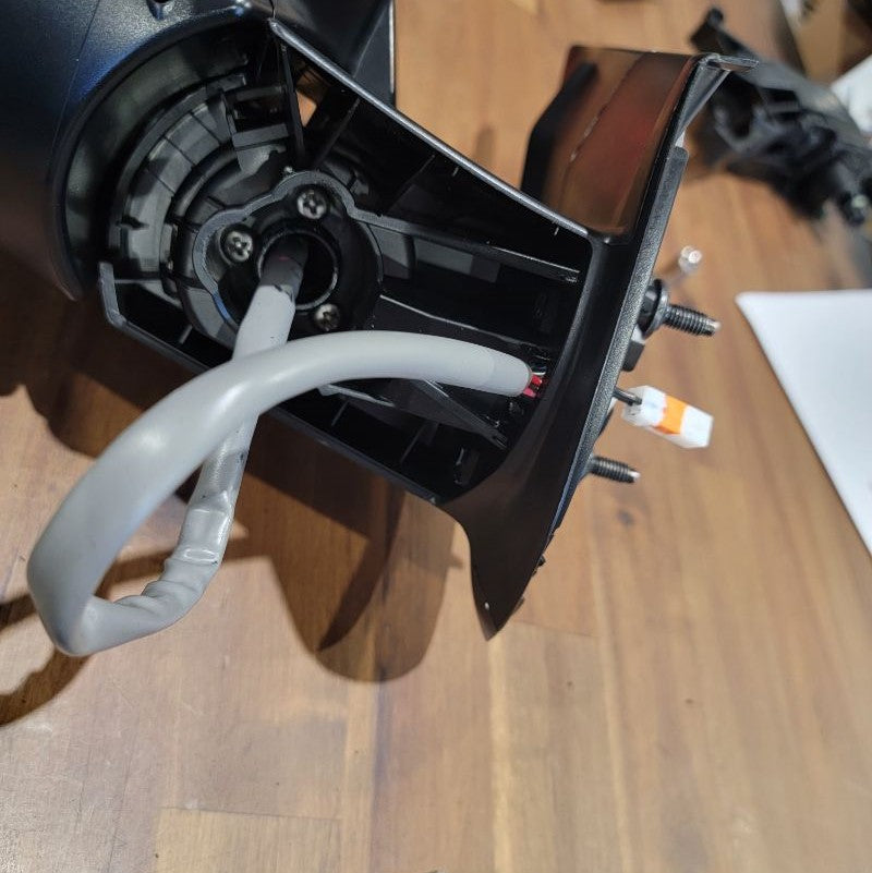
Next, using the supplied screws (three per mirror), mount the mirror assembly to the mirror arm. Make sure that you position the mirror in the unfolded state when screwing the mirror to the arm. You can now route the cable along with the wire guides and out the mounting face. Finish up by re-attaching the lower arm cover and rubber isolator. Hope you noted how to route the wires behind it! In case you didn’t, send the wires around the inner perimeter to the center opening so they can exit out the inner hole of the rubber isolator.
Now, if you didn't do both mirrors at the same time, grab the other mirror at this time and follow Steps 1-8 for the other side. We’re finally done with the mirrors!
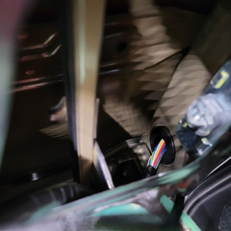
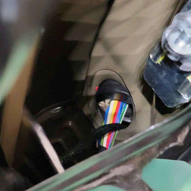
Let’s reattach them to the vehicle with the three original 10mm nuts. Make sure the wires are cleanly pulled through to the inner side of the door. Be careful not to lose your 10mm nuts in between the door panels because they will be lost for good.
Now that we’re done pulling the cable through tight gaps, we can reassemble the two inner connectors into the outer housing and plug it back into the mirror receptacle. The power wires from the motor remain free.
INSTALL IMAGES


STEP 10
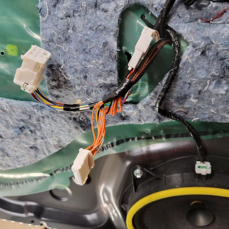
-
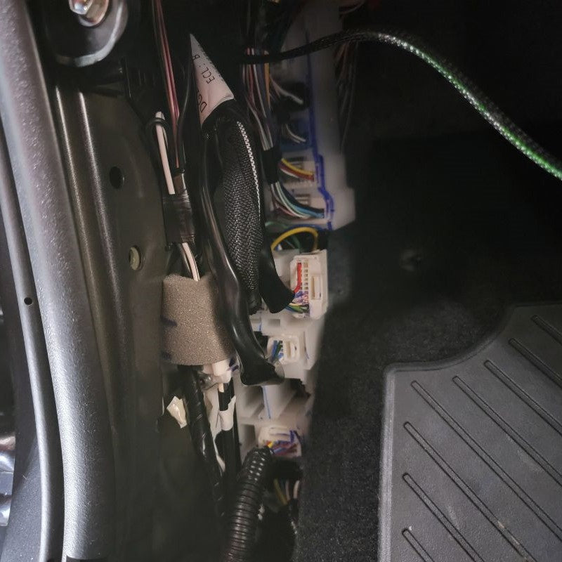
After tidying up the wires, put the kick panel and both door cards back on. Remember to plug in all connectors (window controls, courtesy lights, latch/lock Bowden cable terminations) and check that all snap fits are properly engaged.
Now all you need to do is test your new setup!
INSTALL IMAGES


STEP 11
-
Enjoy your New Power Folding Mirrors!