Your Cart is Empty


FOR TOYOTA HIGHLANDER MODEL
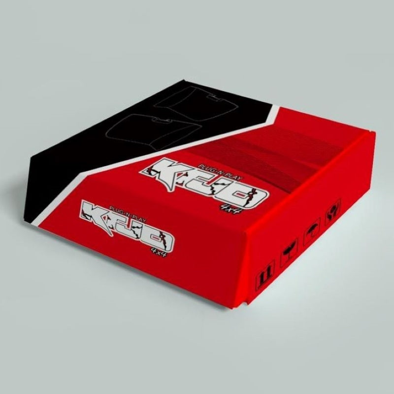
PARTS INCLUDED:1 x Automatic Control Box
2 x Connection Plate
2 x Power Fold Actuator
2 x Actuator Wire Harness
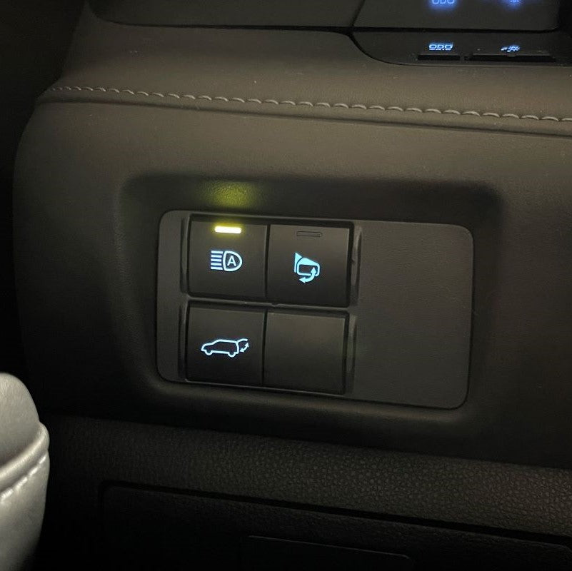
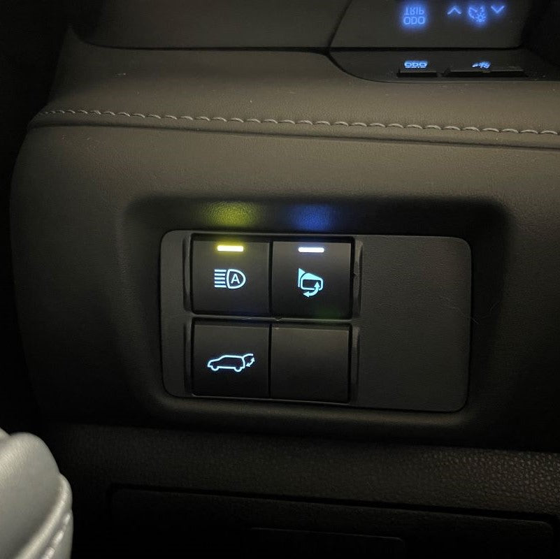
1 x Replacement Adjust & Fold Switch
1 x Adjust & Fold Switch Wire Harness
2 x Extension Wire Harness - Driver/Passenger
1 x Hardware Bag
1 x 3M, Double-Sided Adhesive Sheet
Installation Instructions - Power Folding Mirrors (Located on Website)
1 x Tool, Trim Removal
1 x 1/2-in Socket (10 mm)
1 x 1/2-in Drive Ratchet
1 x 1/4-in Phillips Screwdriver
1 x T15 Torx Screwdriver
1 x Dremel
1 x 1/8-in Flat Head Screwdriver (optional)
1 x Fish Tape Wire Puller (optional)
Electrical Tape (optional)
Zip Ties (optional)
Door Panel Remover (optional)
DISCONNECT THE BATTERY BEFORE YOU BEGIN INSTALLATION
Must Press + to see the narrative on each Step
-
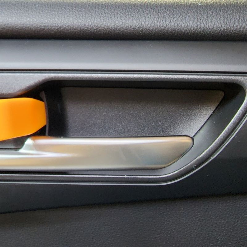
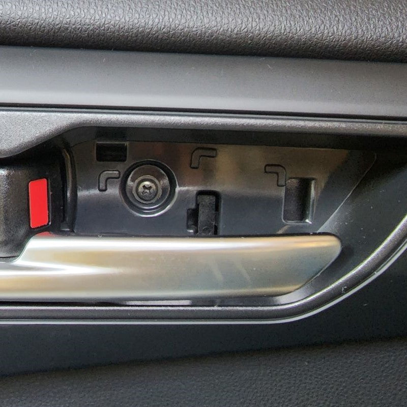
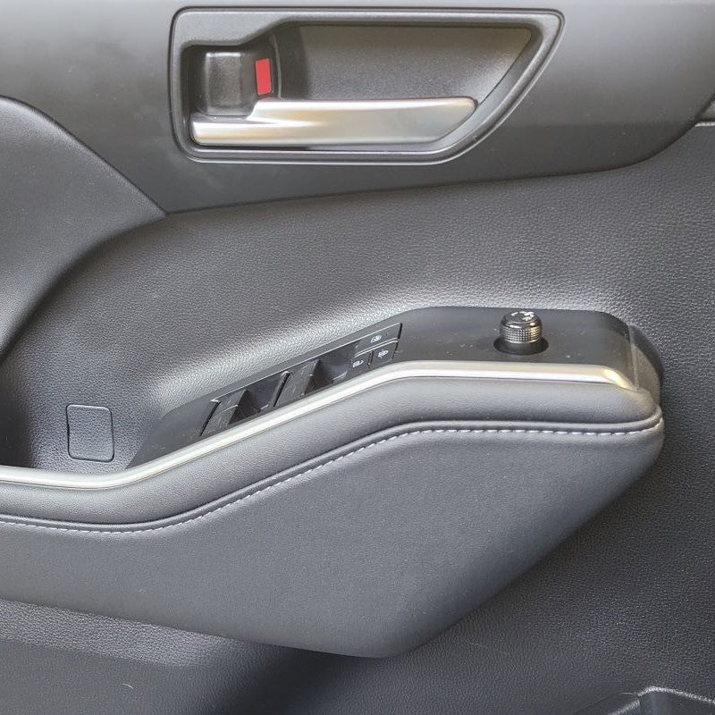
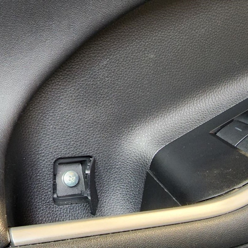
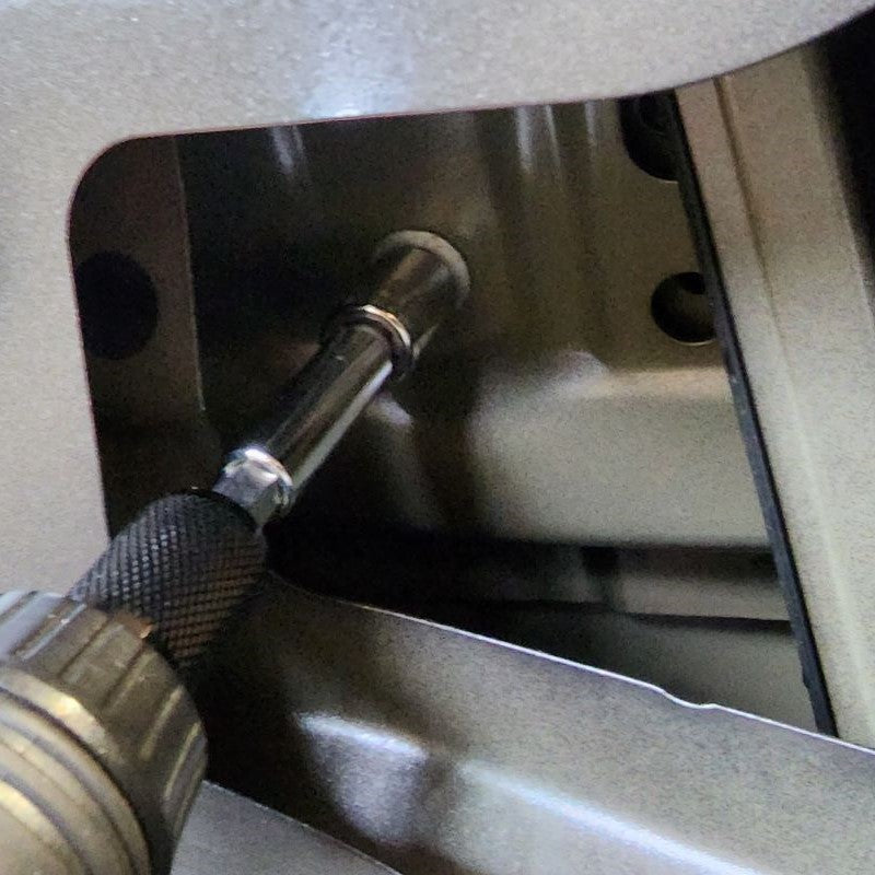
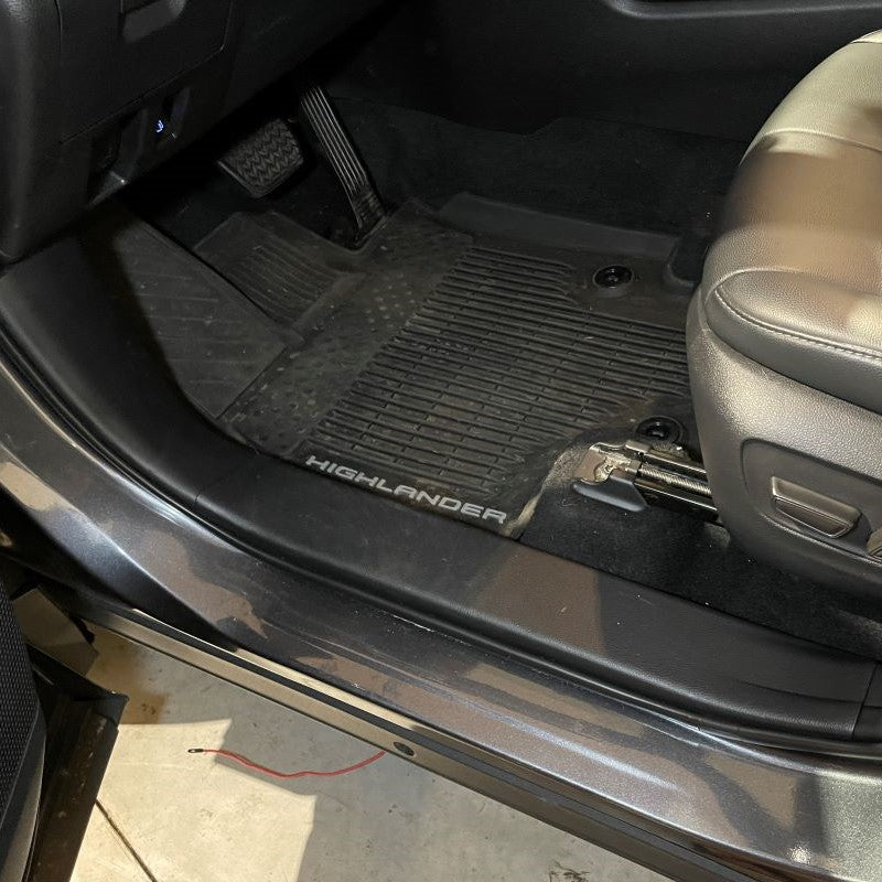
Start by removing the two fixing screws inside the driver's door panel.
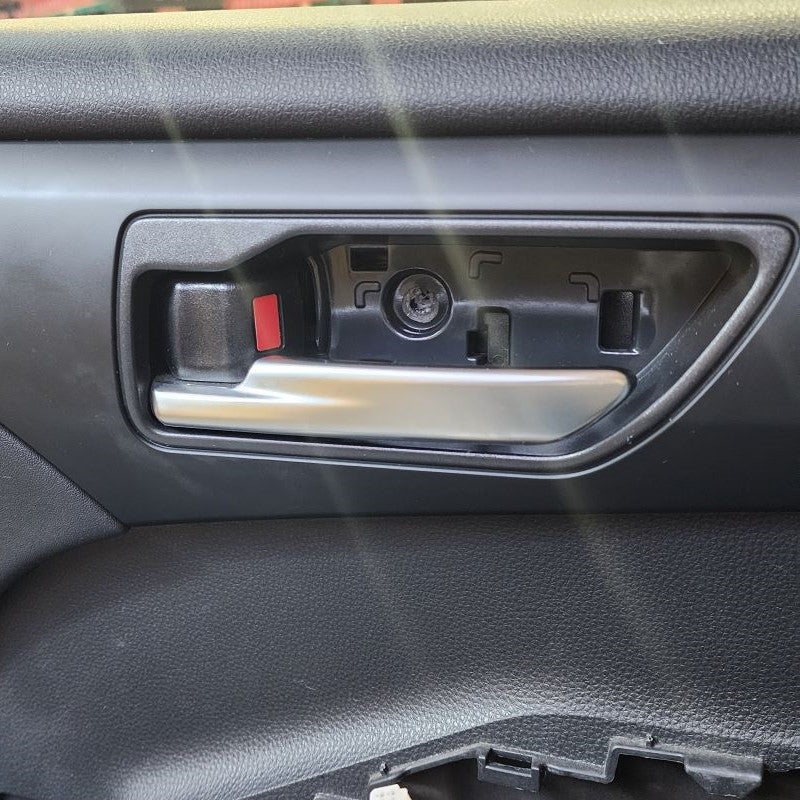
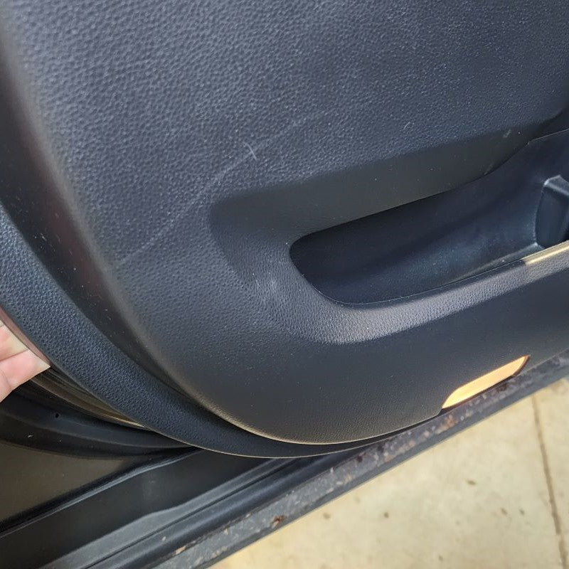
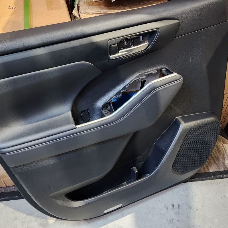
The first hidden screw is behind the door bowl hole cover. Using a trim removal tool if you have one or something like it, start on the left side closest to the door handle. Pry outward away from the door panel from behind the hole cover. It may be easier to pull the door handle out to create more space. Take a screw driver and remove that screw. Set it aside for now.
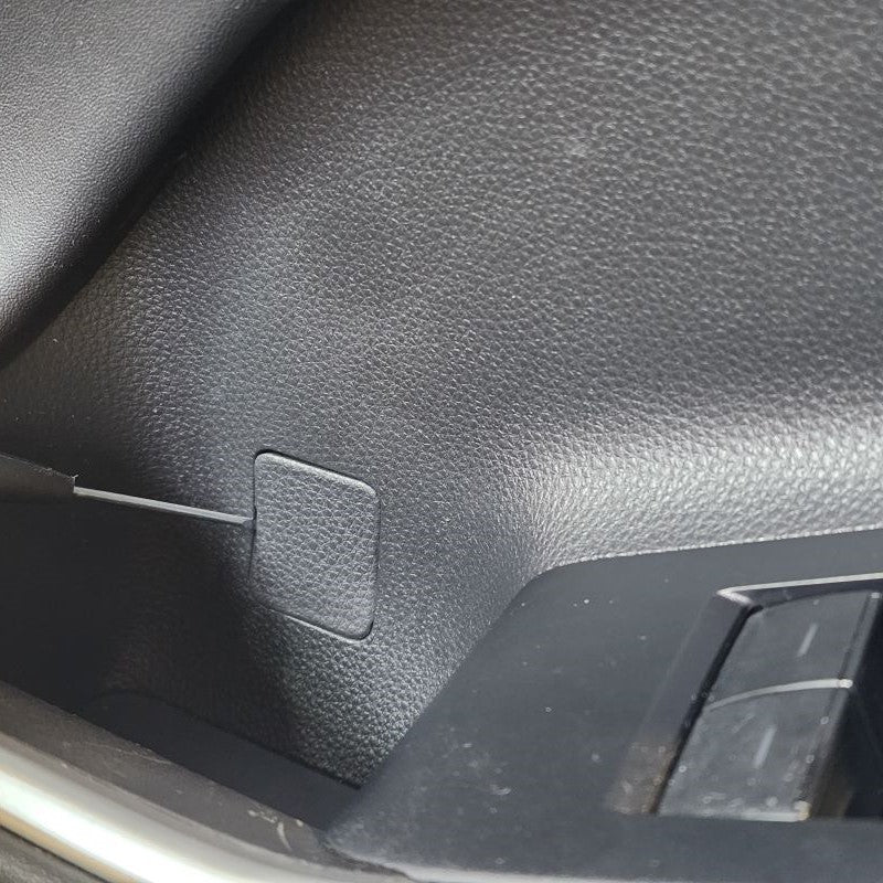
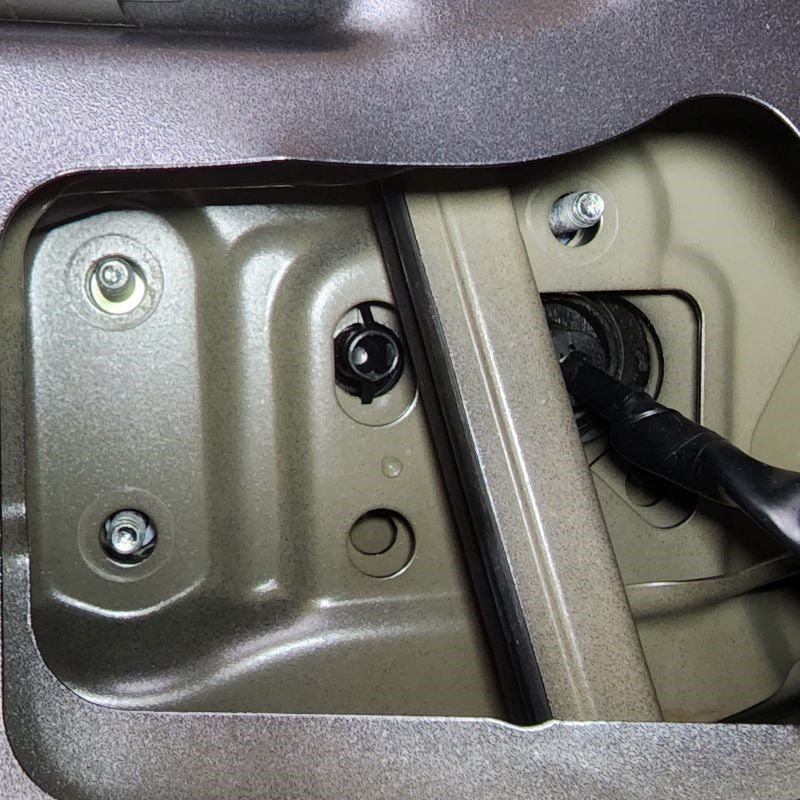
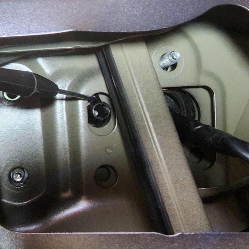
The second hidden screw is behind the littel square door panel cover piece located near the door handle pocket. Use something small or your trim removal tool to pop up the cover. Take a screw driver and remove that screw. Set it aside with the first screw for now.
STEP 1
INSTALL IMAGES


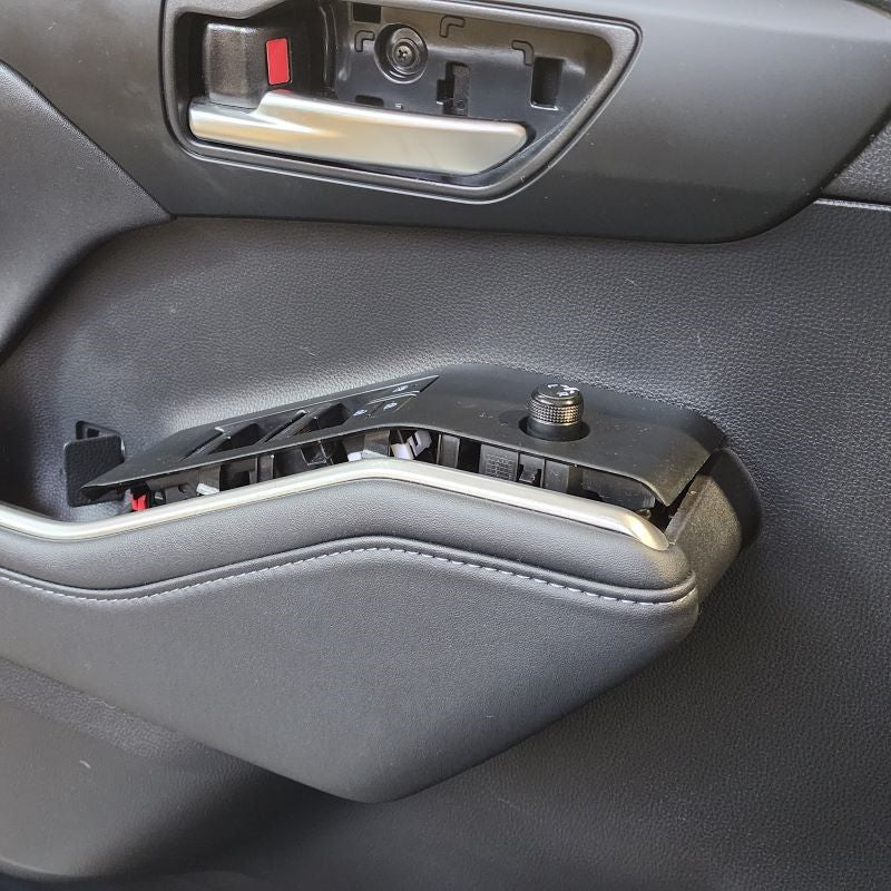
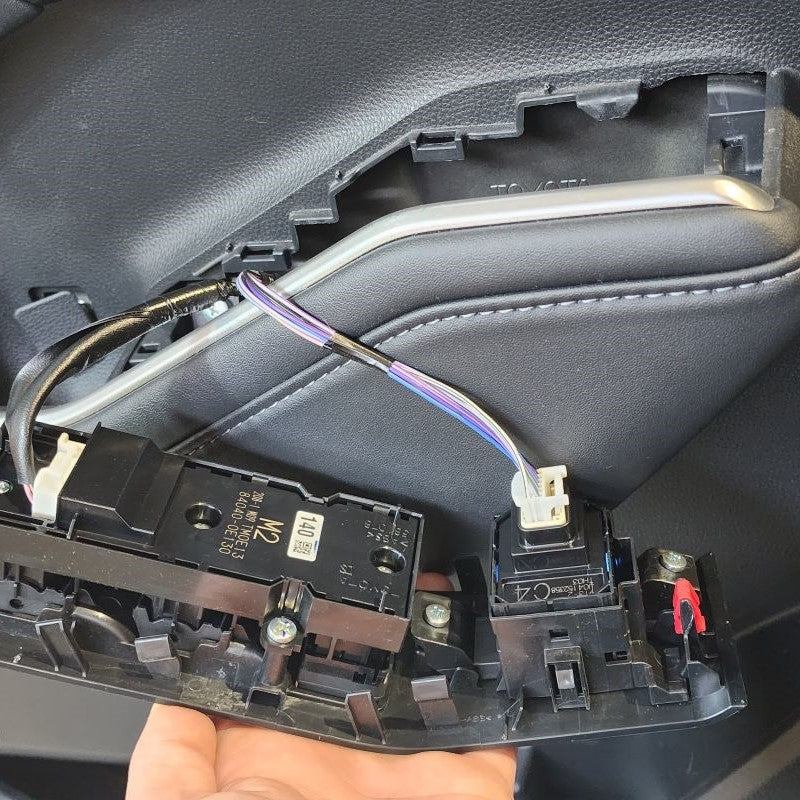
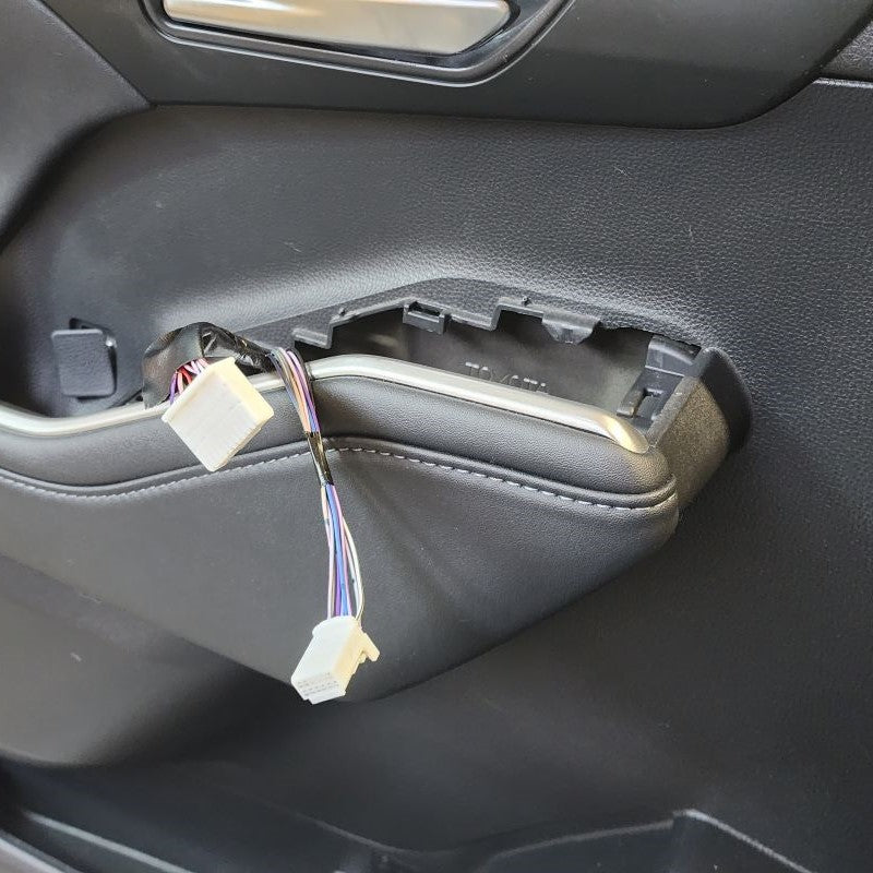
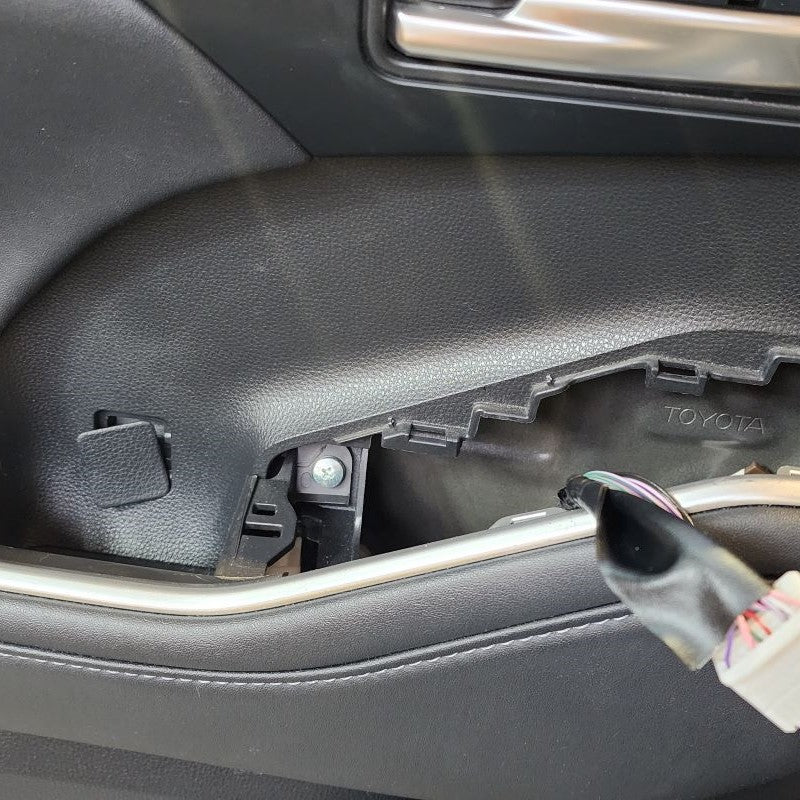
STEP 2
-
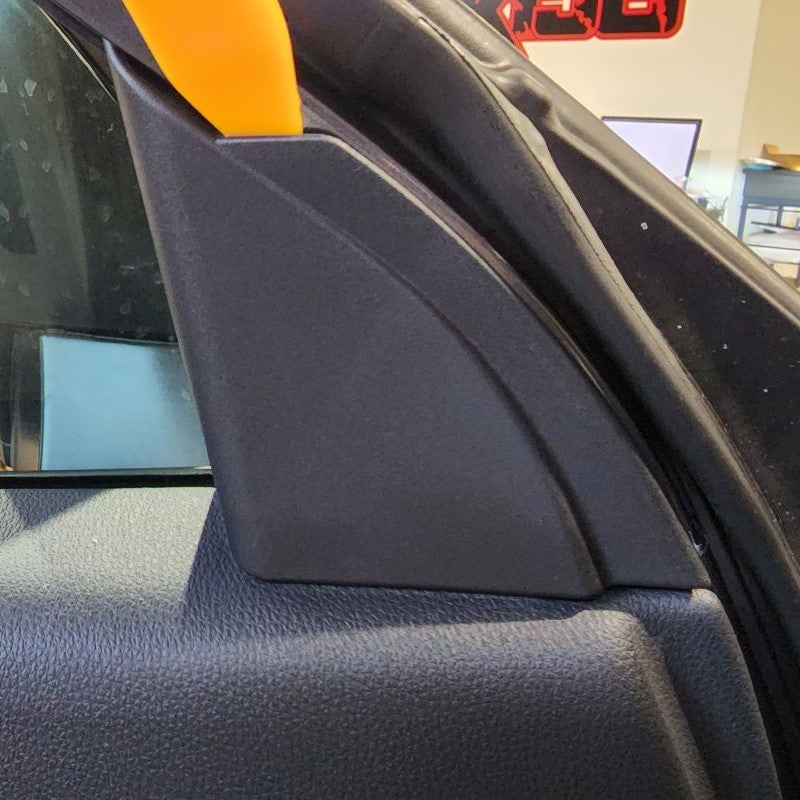
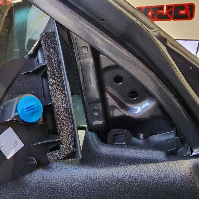
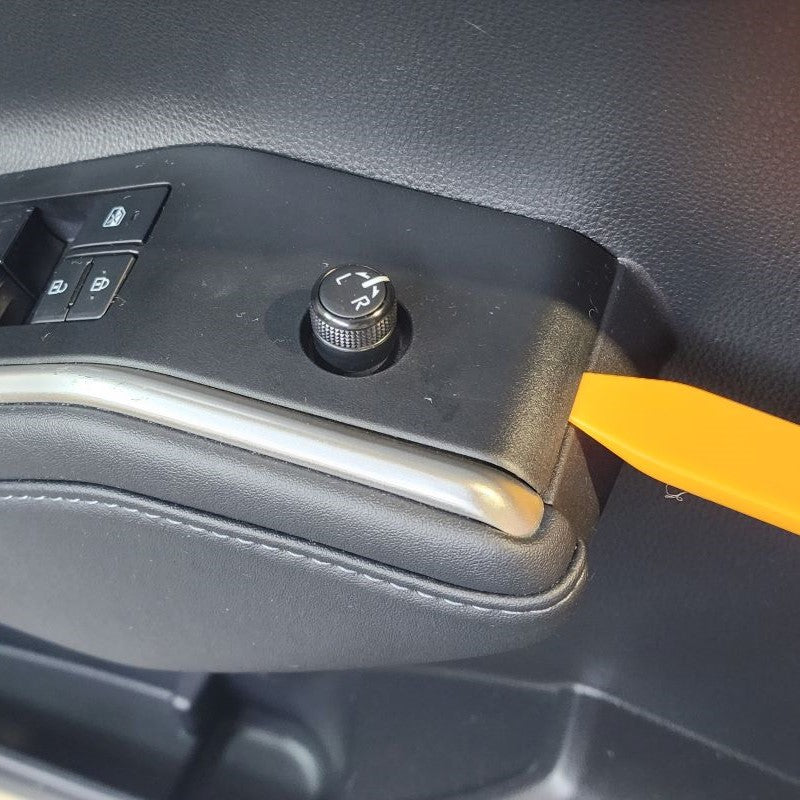
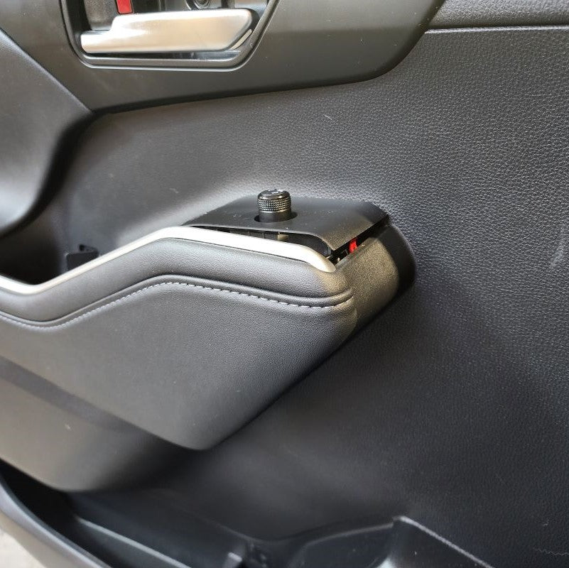
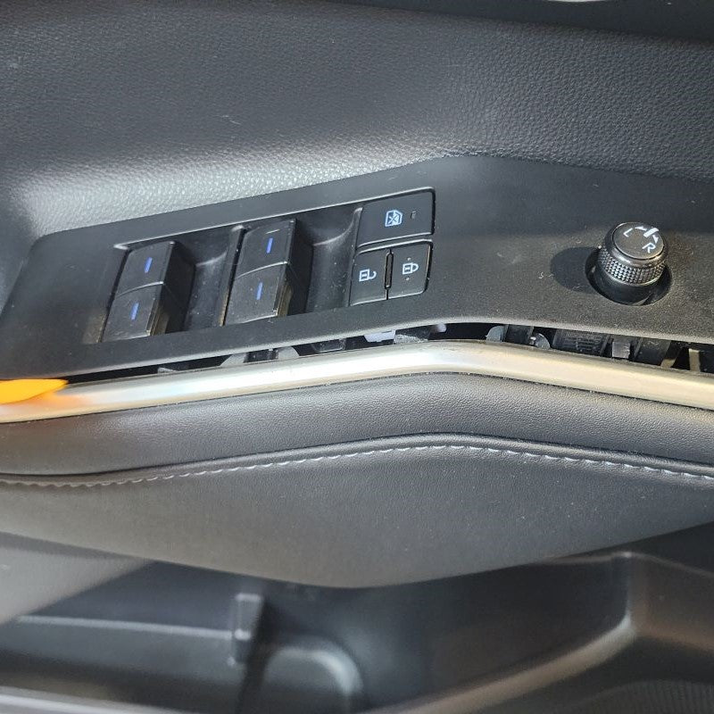
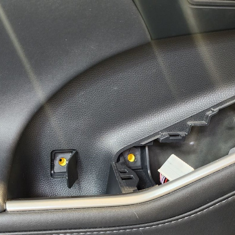
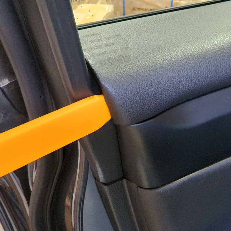
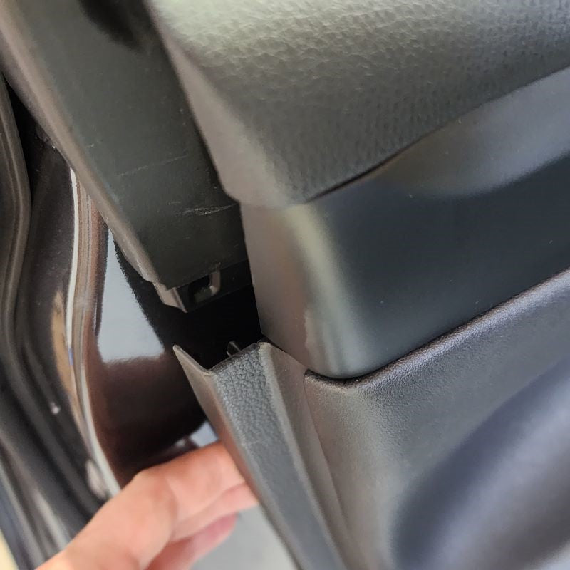
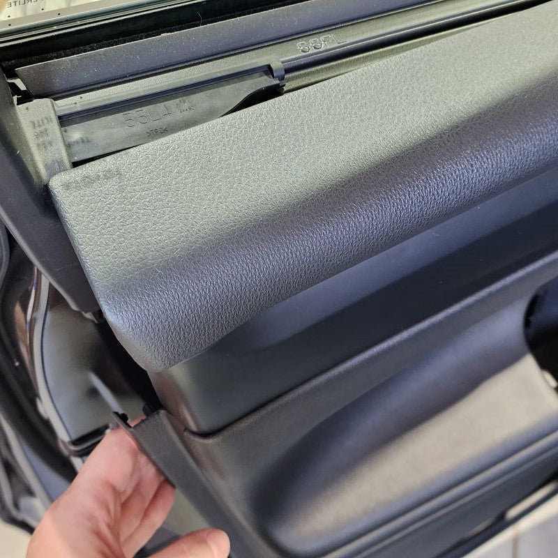
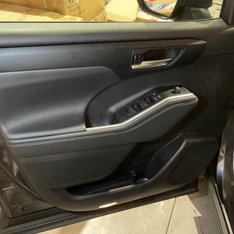
Start by removing the triangle trim panel in the upper right corner of your door. It is held in with three plastic fasteners. Pull straight out away from the door and it will release. Be aware, some of the plastic fasteners may stay in the door. Remove these and reinstall them on the trim panel for reinstallation later.
Following that, in preparing the door panel for removal, you will need to remove the window switch trim panel. Again, using a trim removal tool or something like, pry upward to release the tabs from the door panel underneath. Disconnect the factory connectors at this point and set the window switch panel aside.
Lastly, there is one more hidden screw that is revealed once the switch panel is off. Take a screw driver and remove the screw. Set aside for now.
INSTALL IMAGES


STEP 3
-
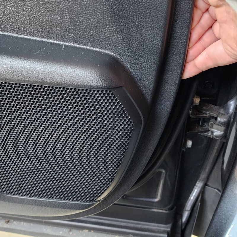
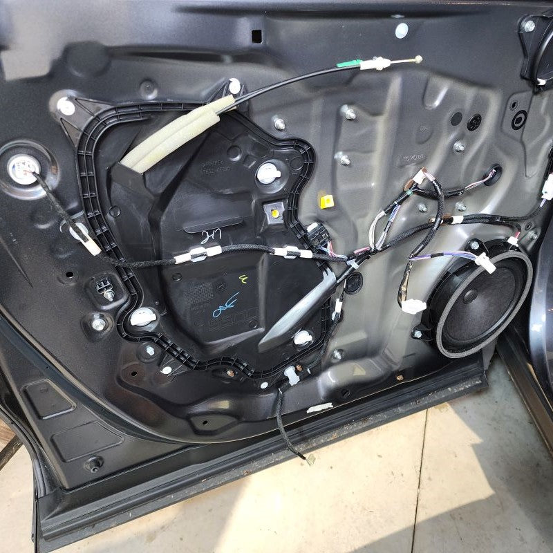
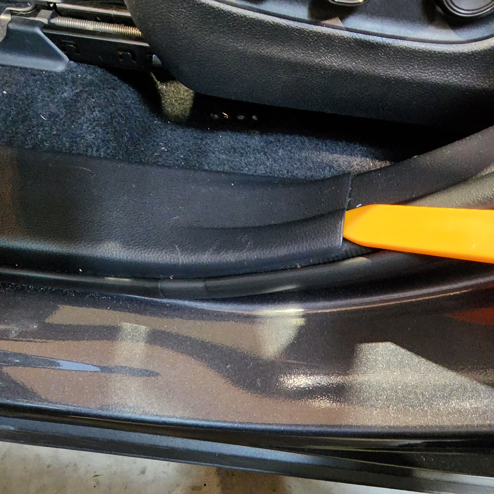
Using your handy trim removal tool or hand, begin in the lower right corner and start separating the door panel from the door frame. Slowly work your way around the bottom and sides, popping off each successive snap until you’re left with the door panel hanging by the top lip.
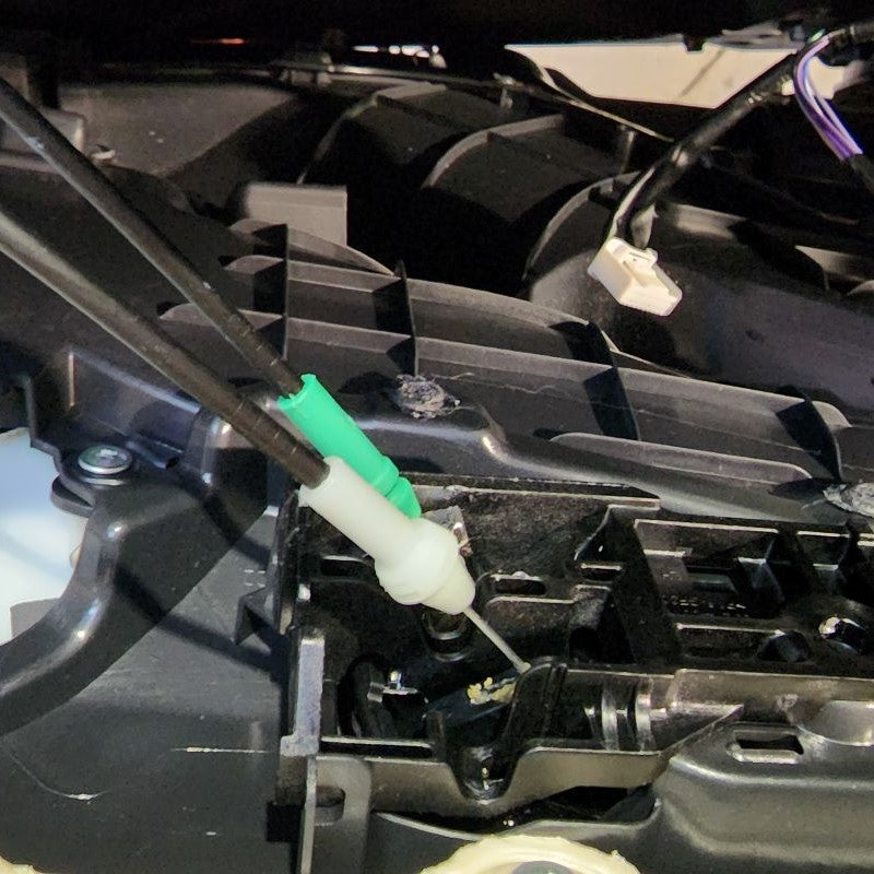
In order to remove the door panel, pull it up and straight back off the door frame at the top lip. Make sure not to pull the door panel too far away from the frame – we still need to deal with the latch and lock cables.
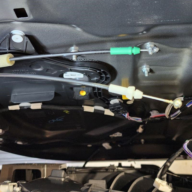
If you look behind the door panel you just pulled off, you’ll see one white and one green Bowden Cable termination. Carefully snap these out of the black housing and maneuver the steel cable ends out of their enclosures. If you should see anymore white connectors that may be connected to your door panel, this is the time to unplug them as they may be the last connections standing in the way of removing the door panel completely from the door frame.
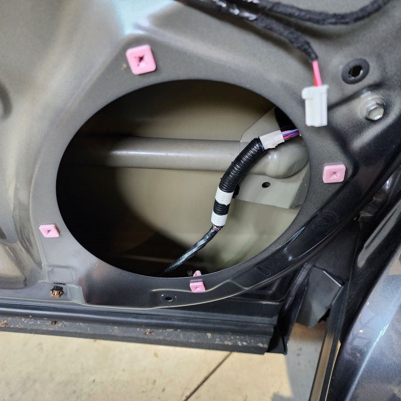
Finally, at this time look around your door frame and make sure all of your white fasteners were removed with the door panel. If there are some still in the door, remove them and reinstall the missing fasteners back in your door panel for later.
INSTALL IMAGES


STEP 4
-
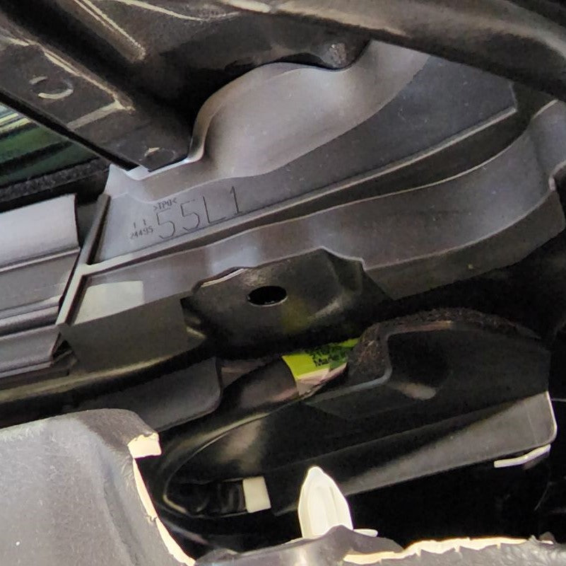
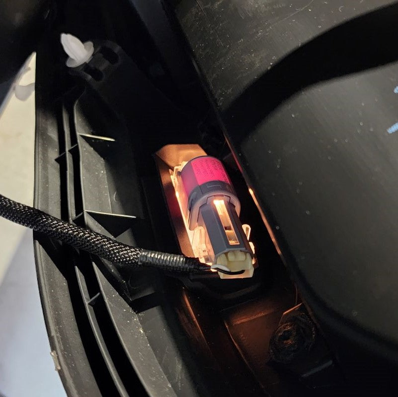
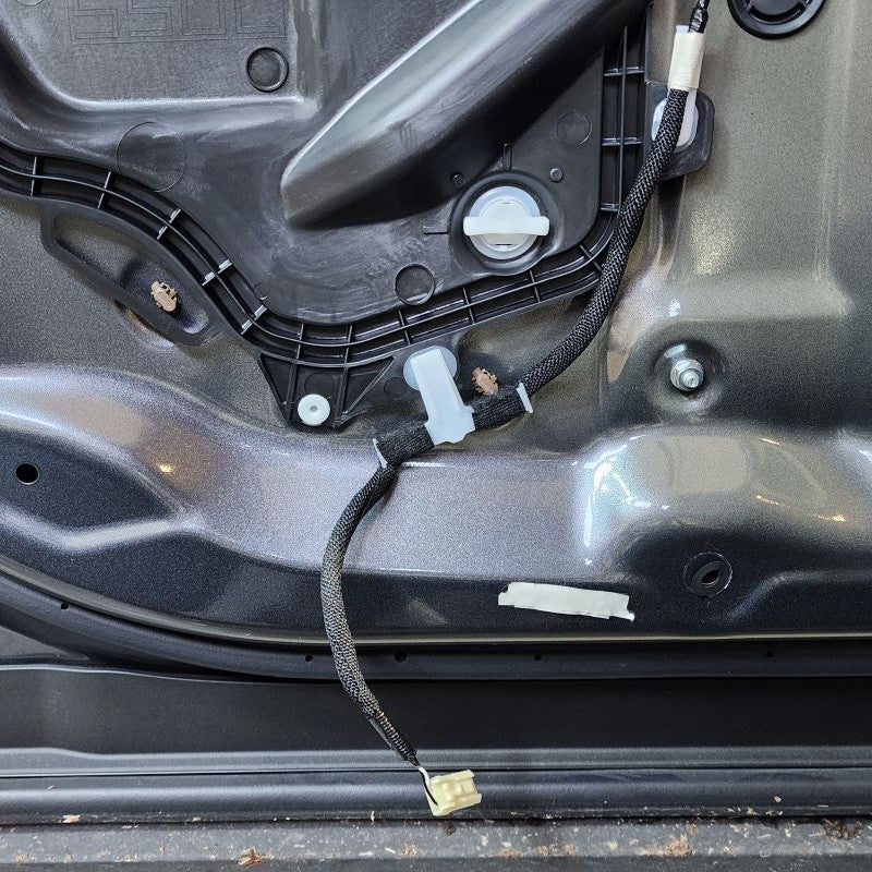
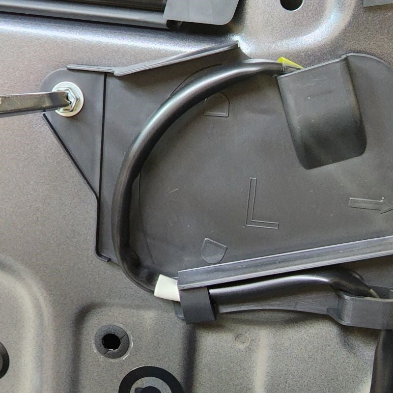
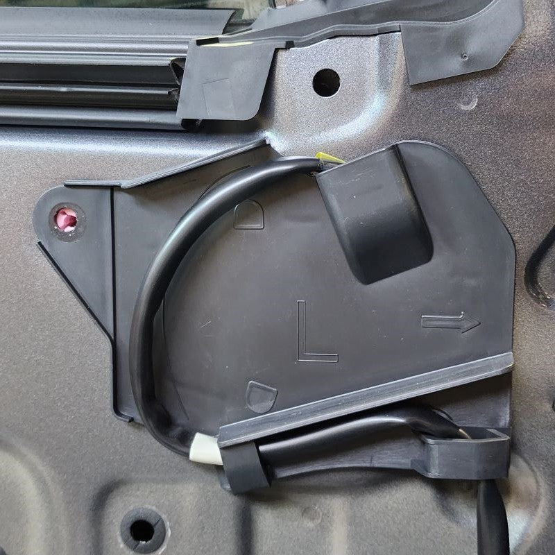
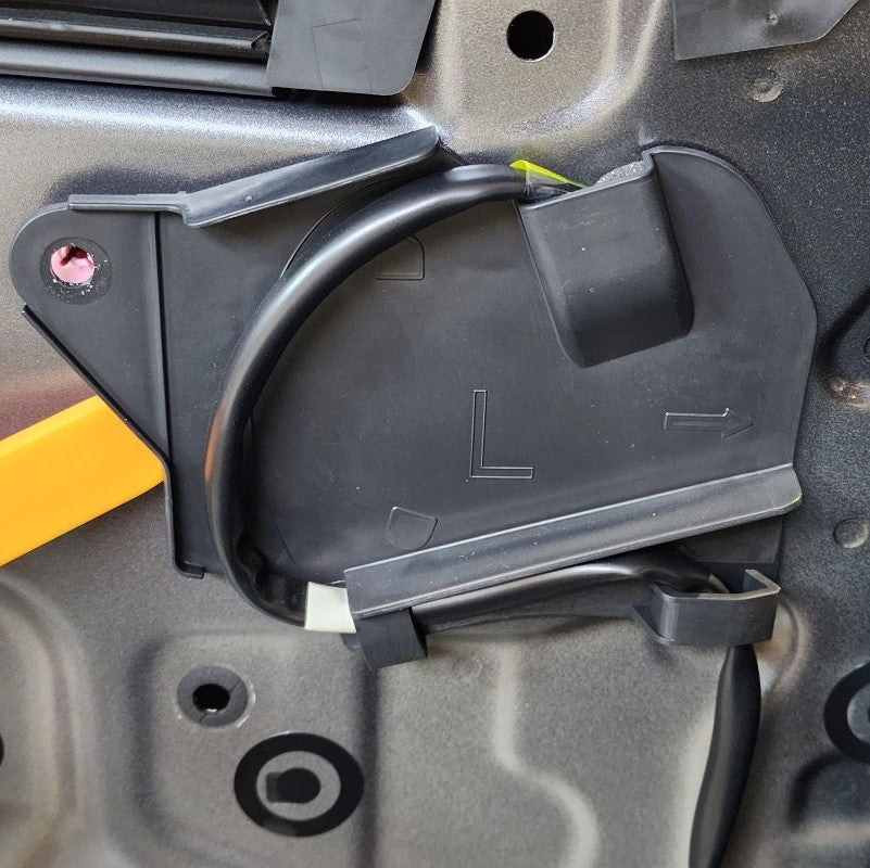
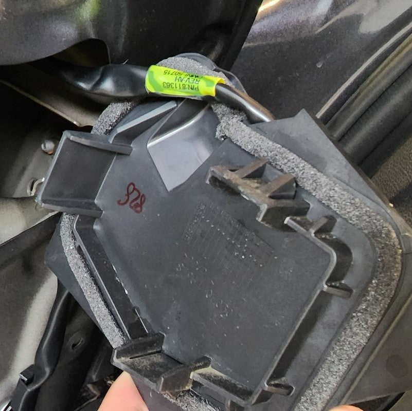
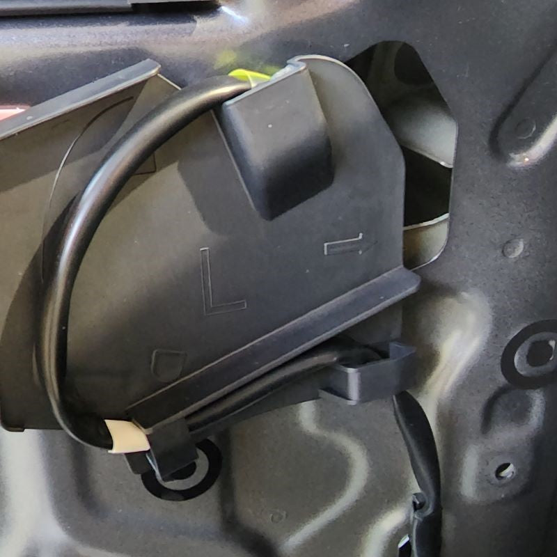
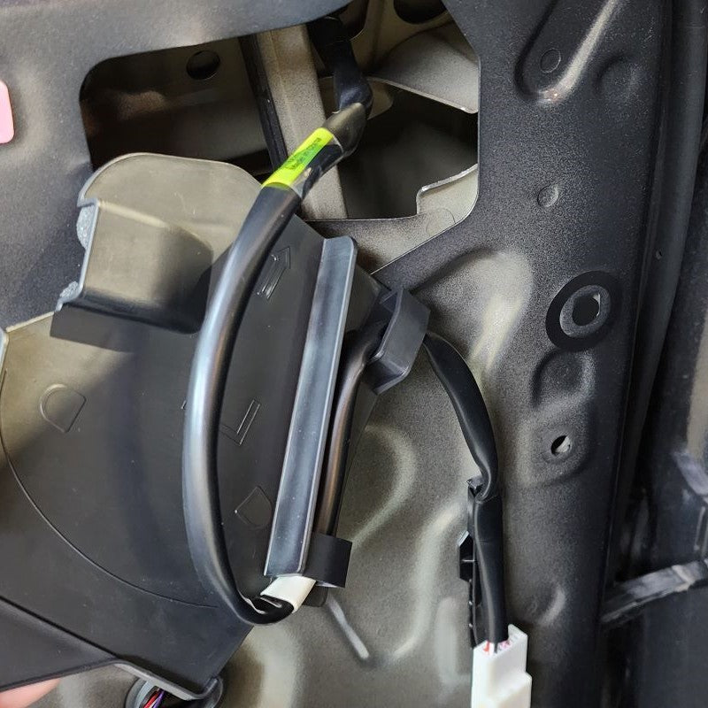
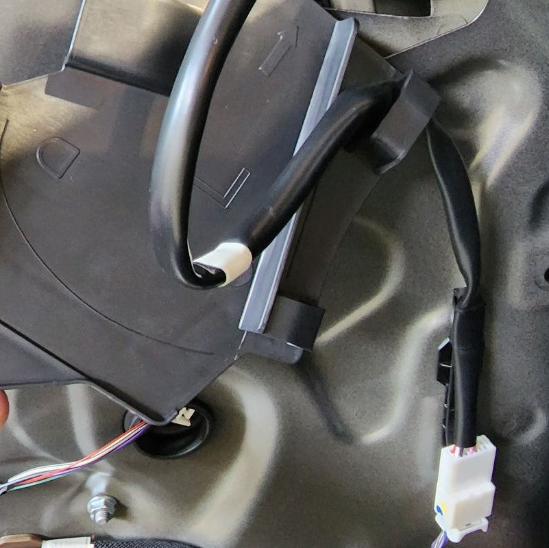
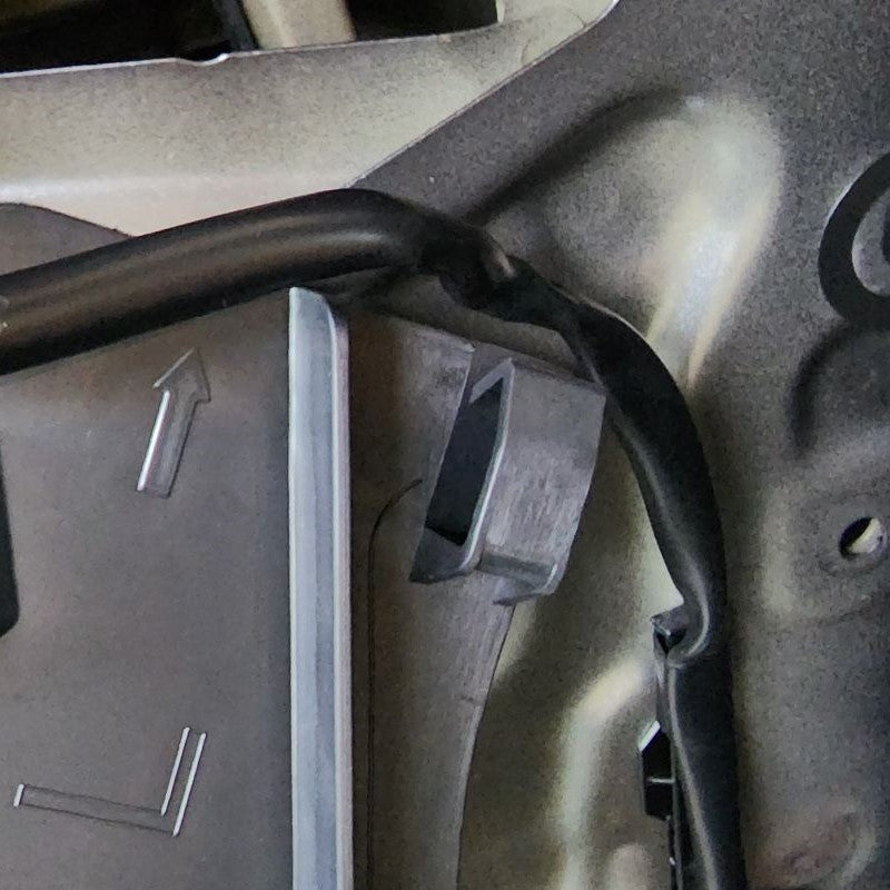
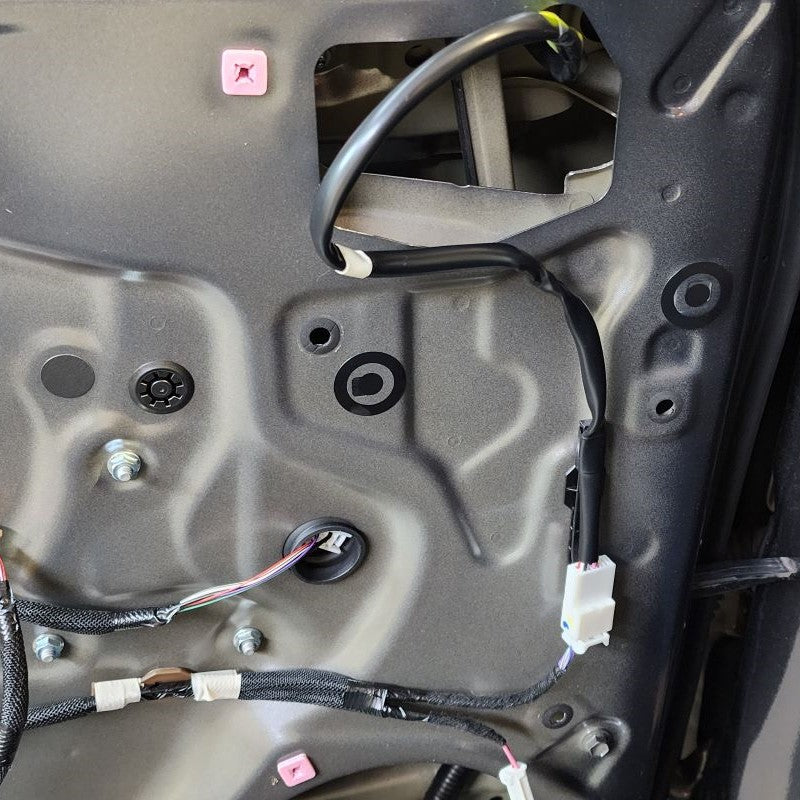
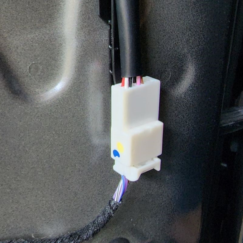
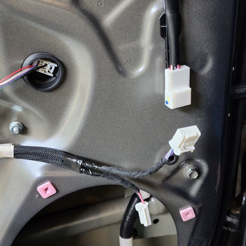
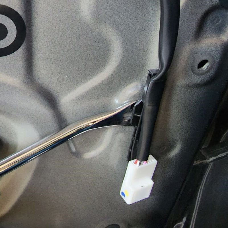
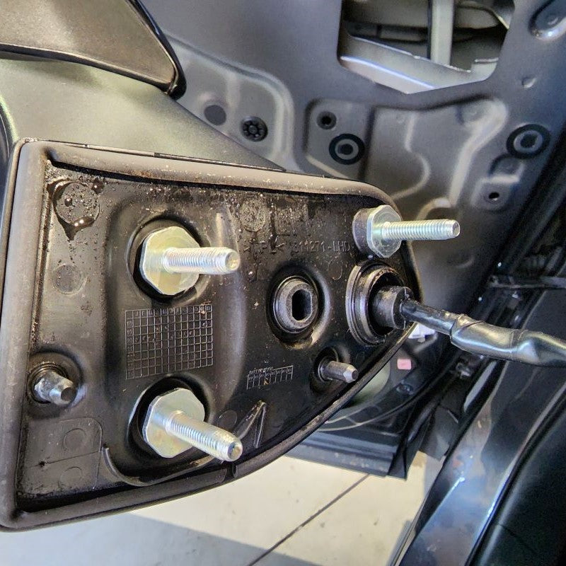
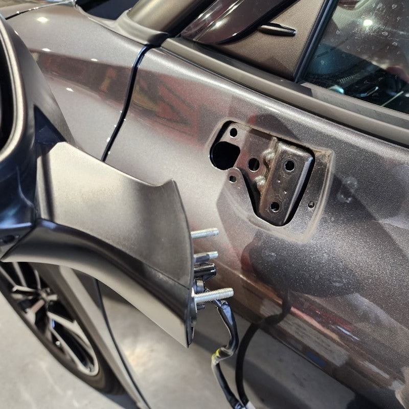
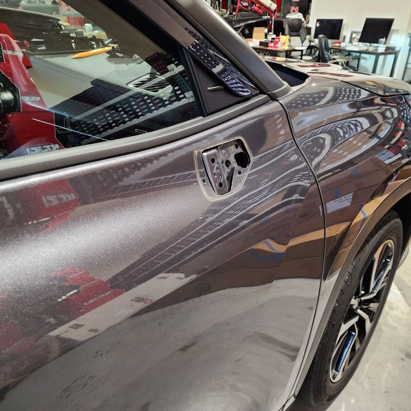
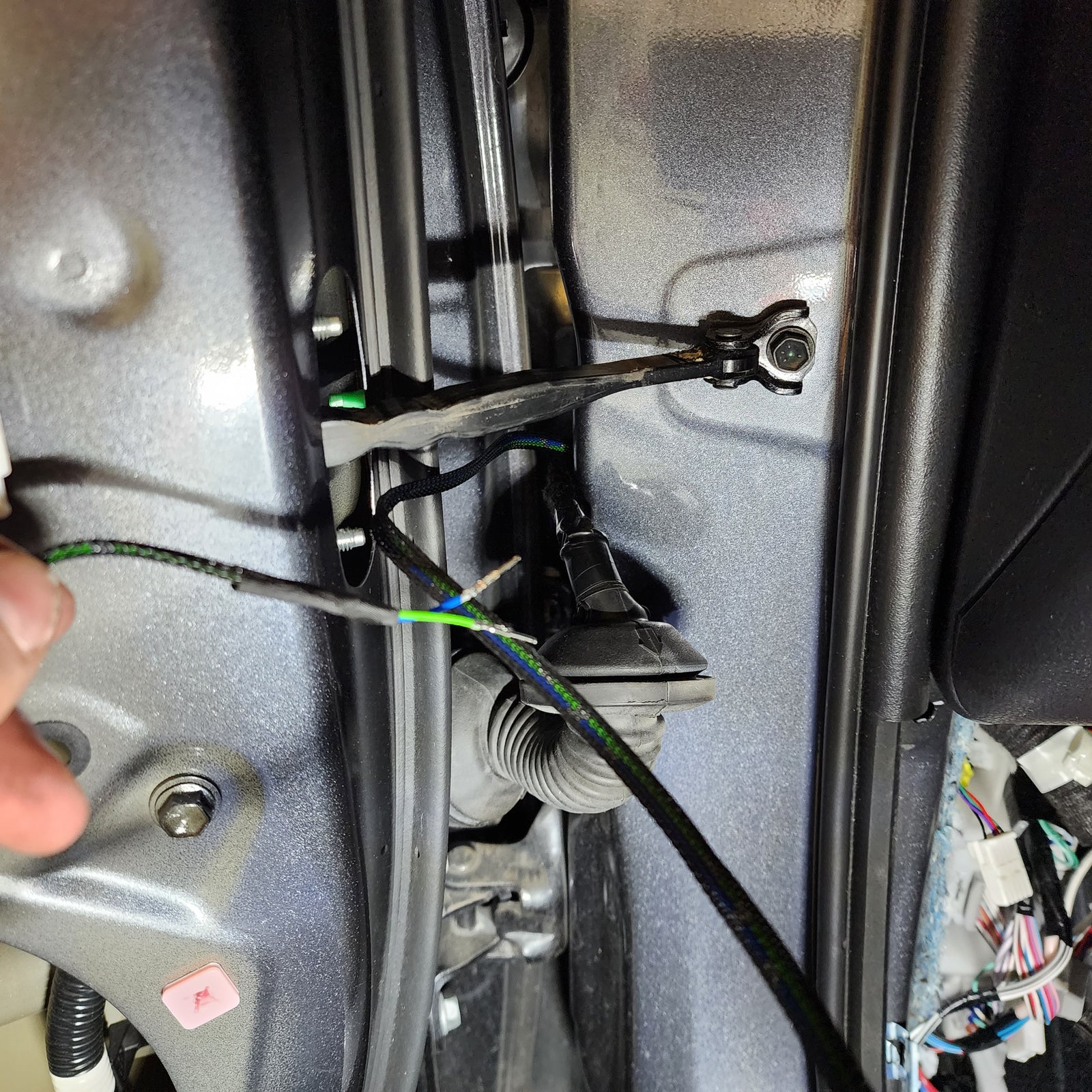
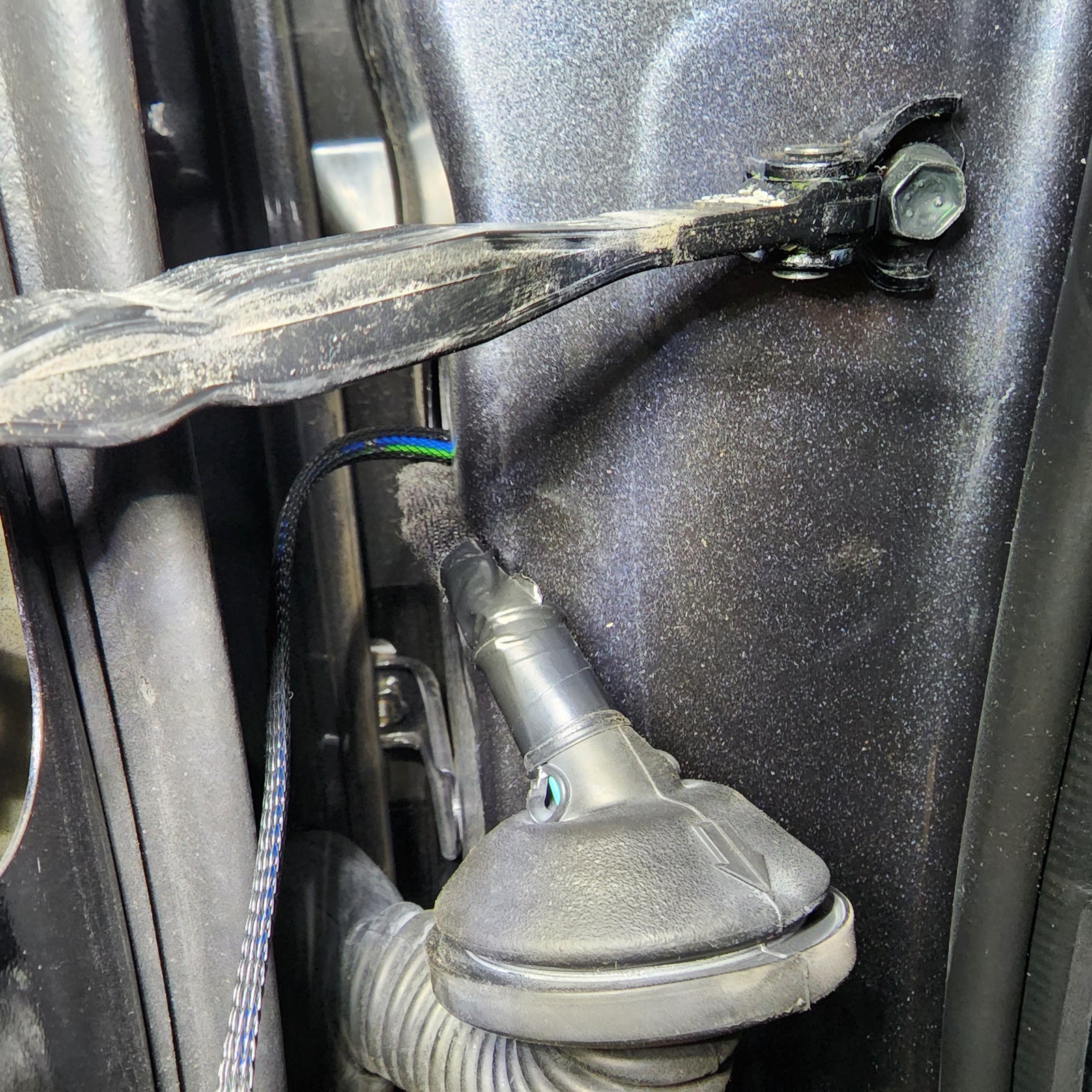
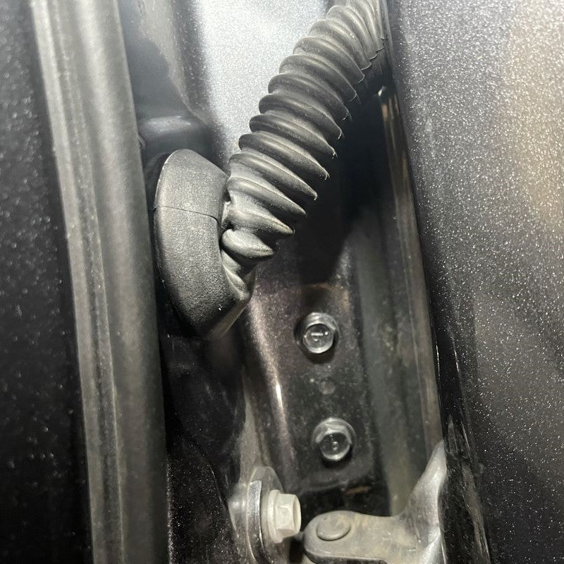
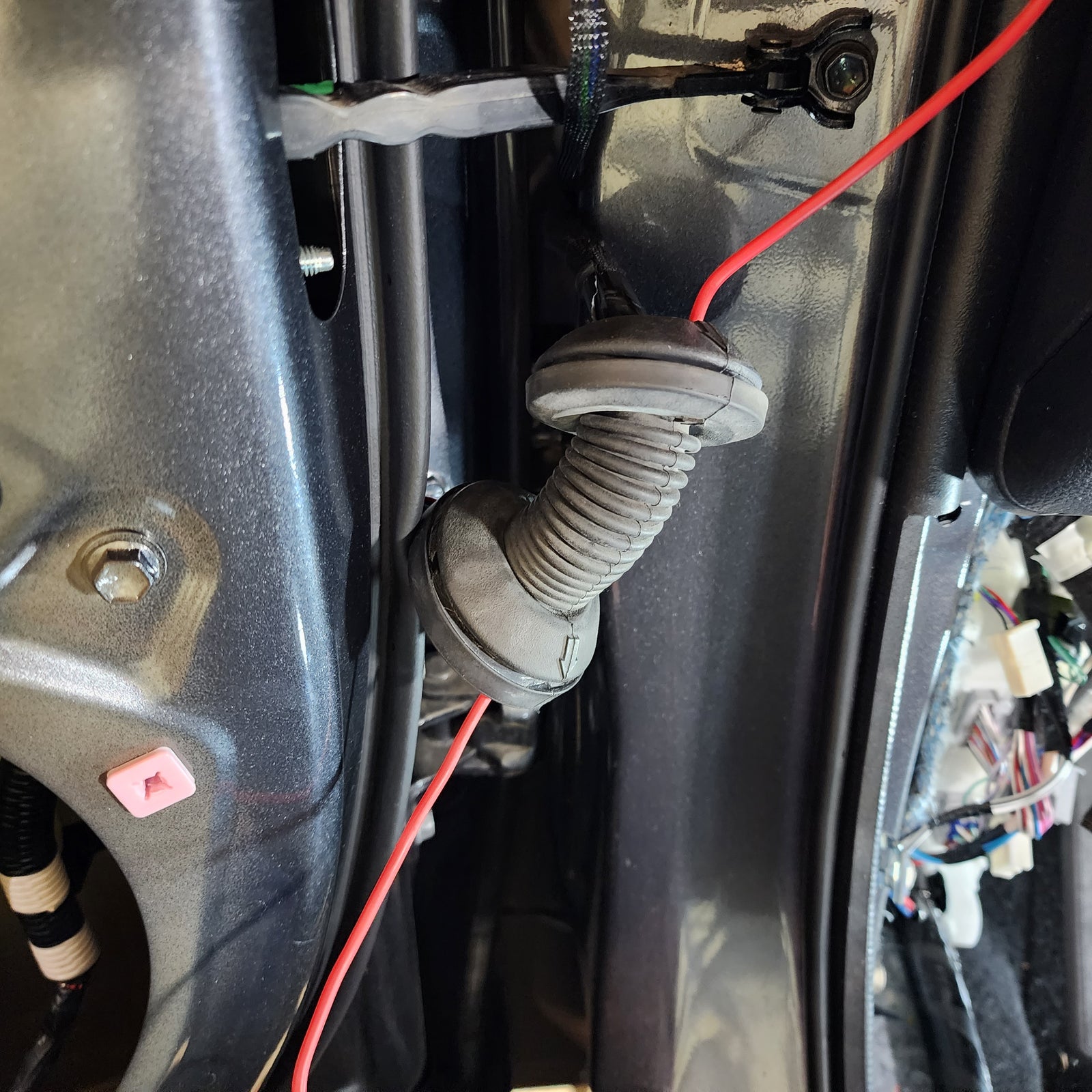
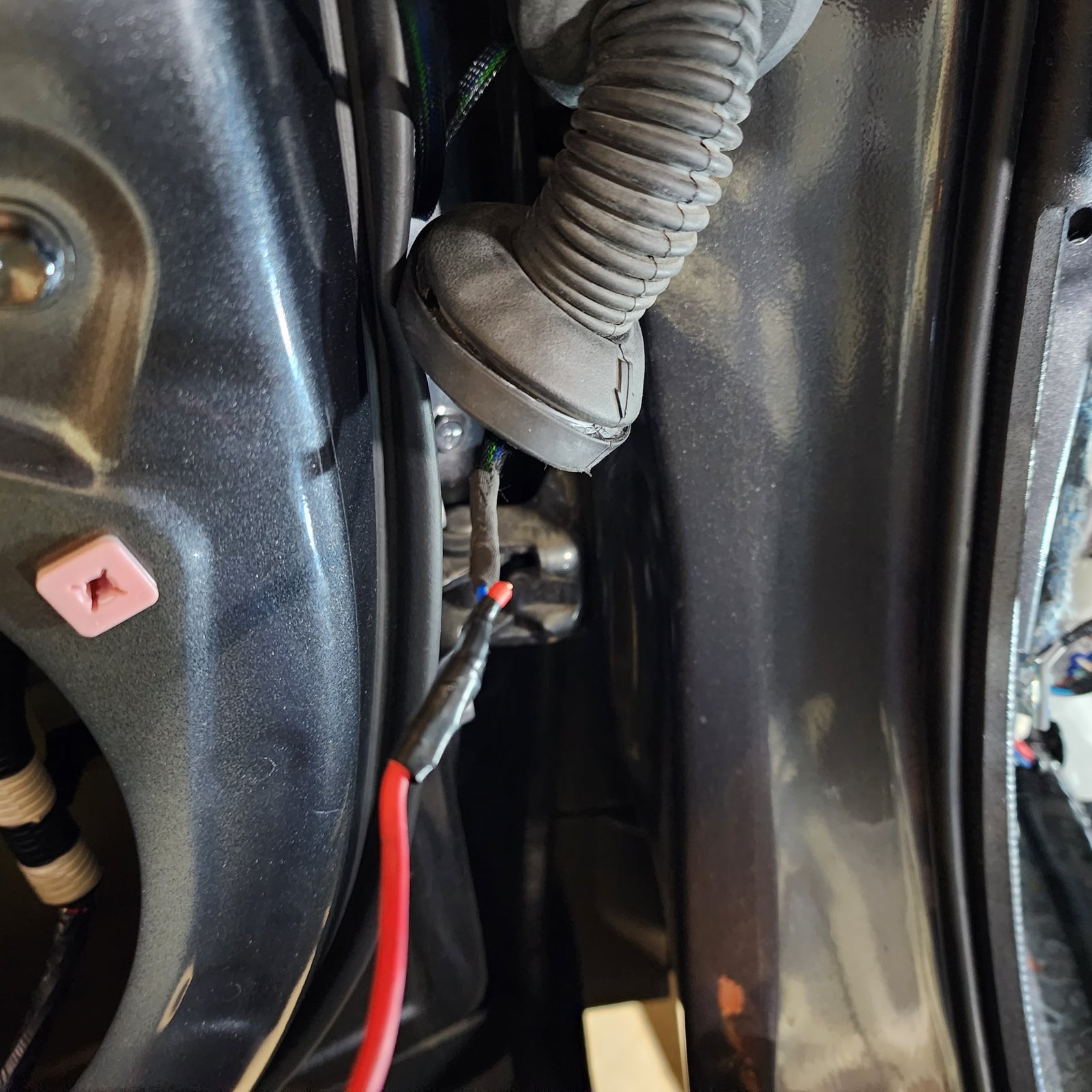
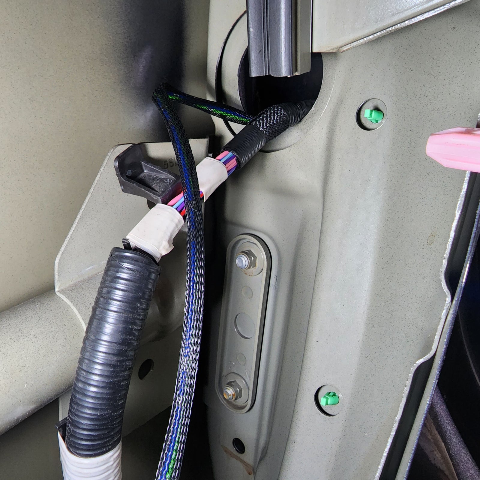
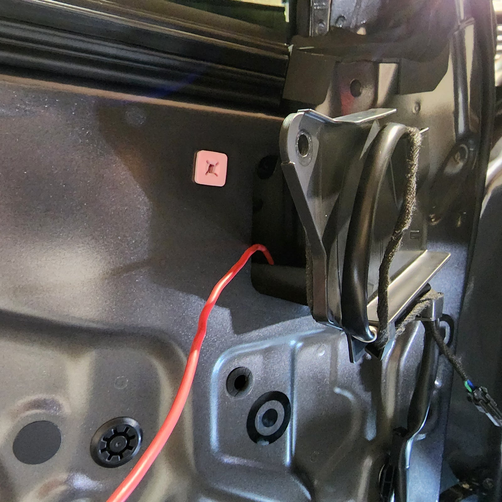
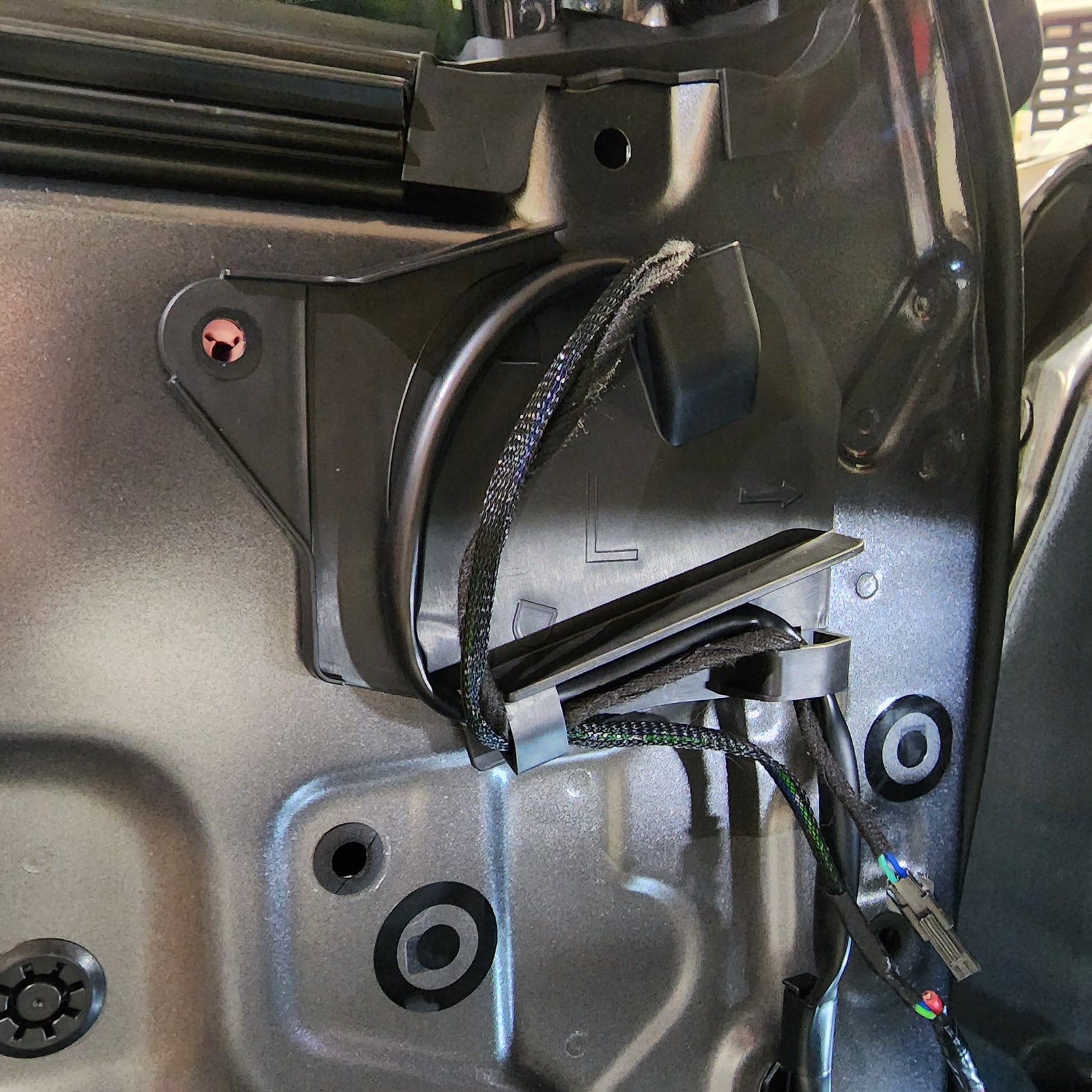
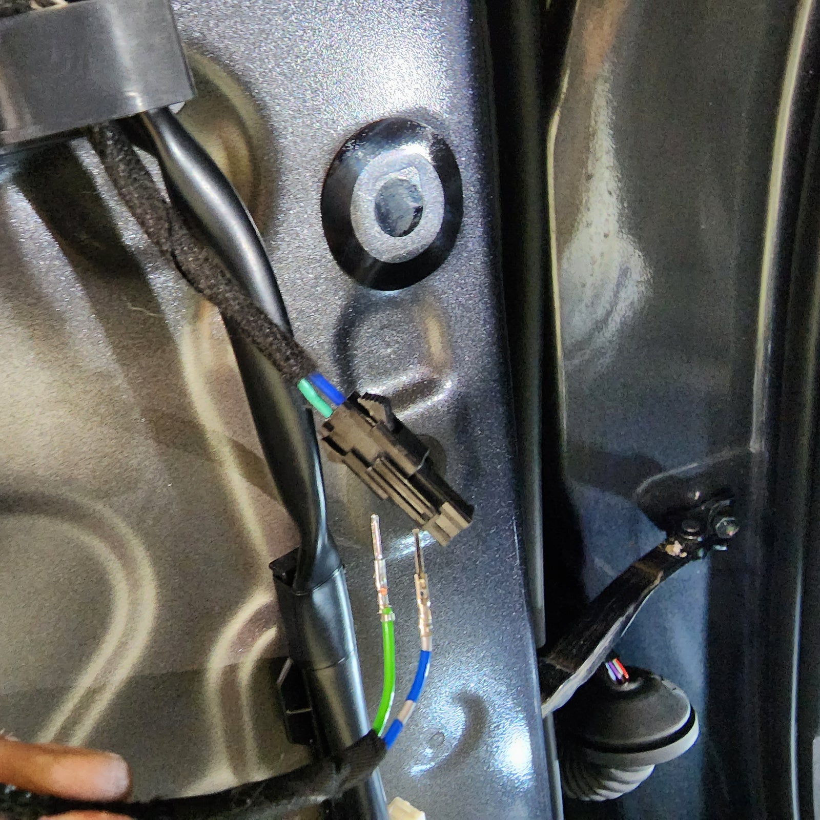
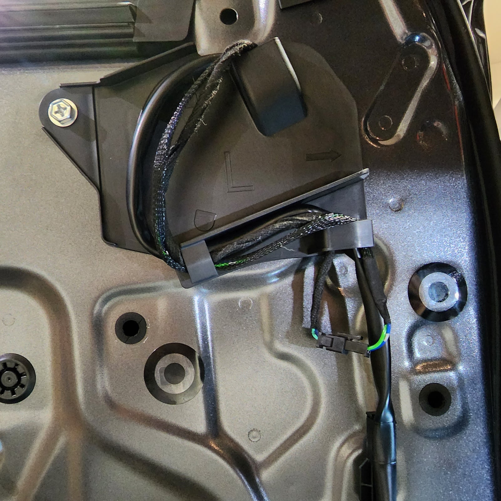
With now having the door frame exposed, we can easily find the mirror connector – just follow the wire that’s coming out of the mirror and routing down to the white connector at the top right side of the door. Remove the connector and any tape holding the cable in place.
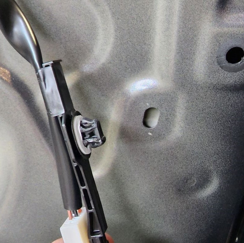
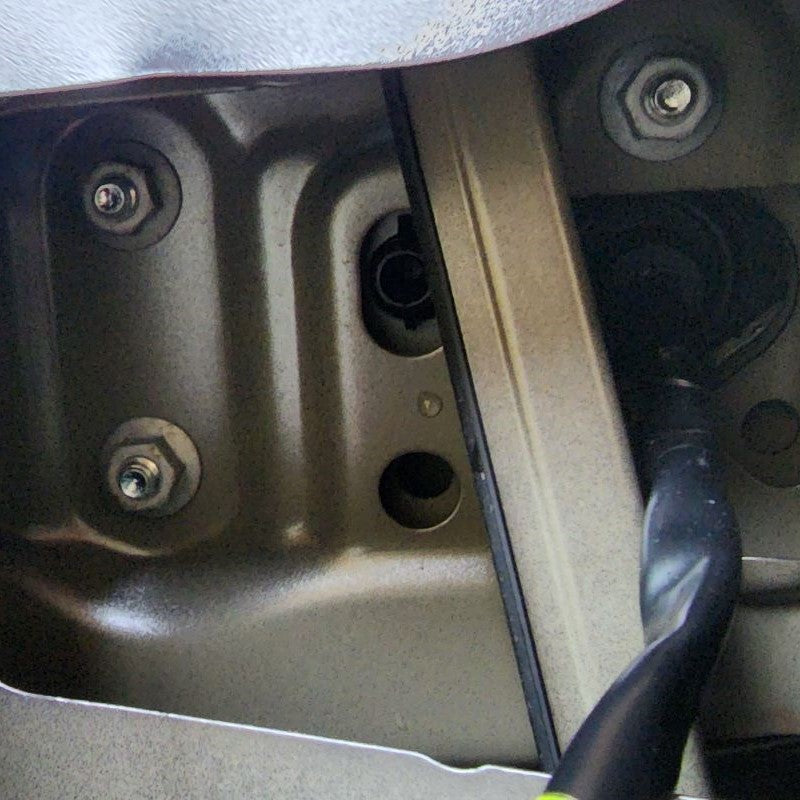
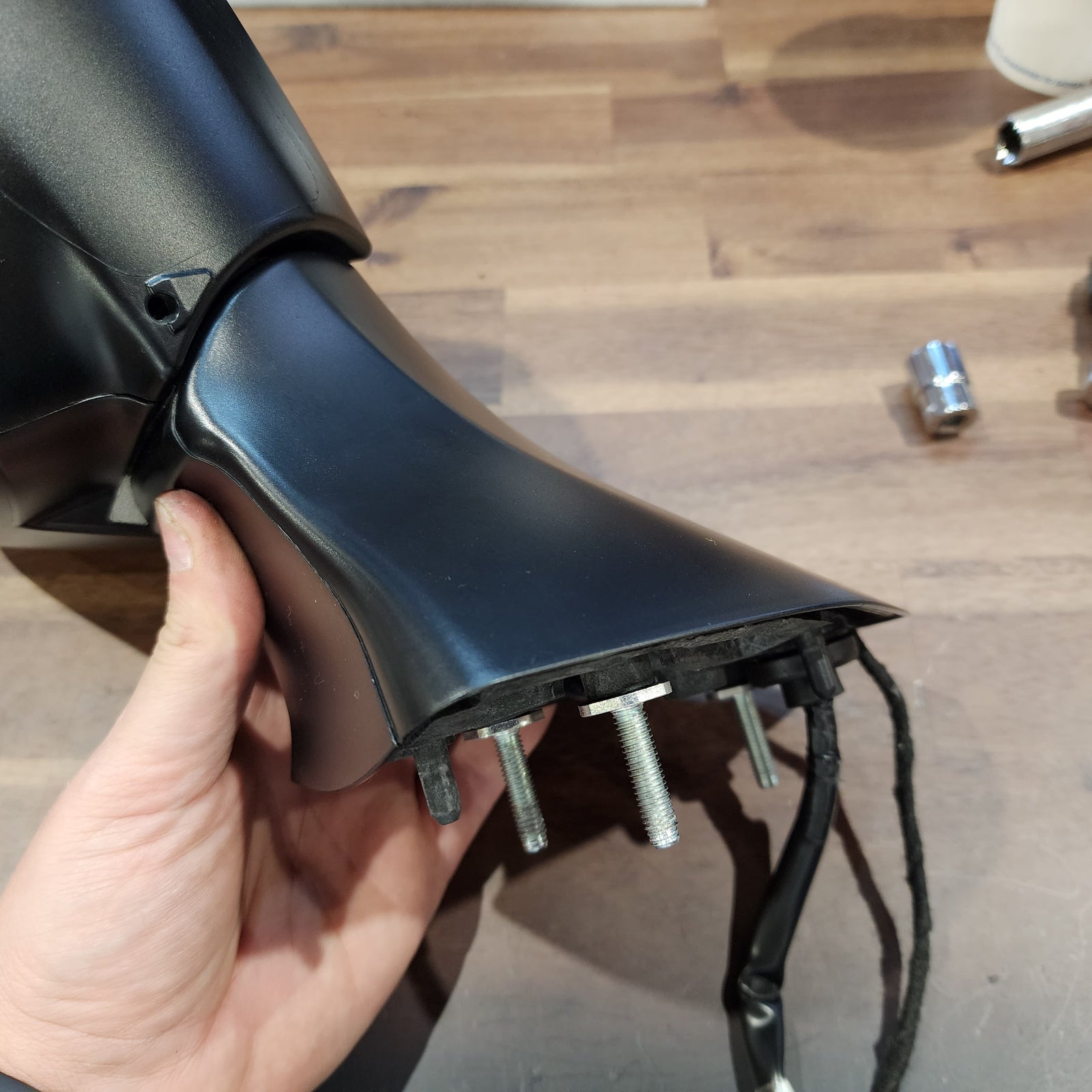
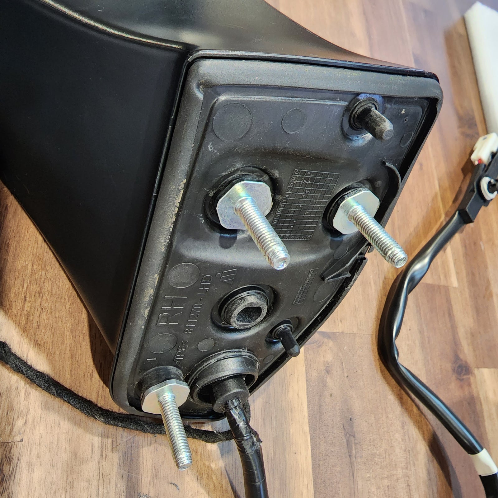
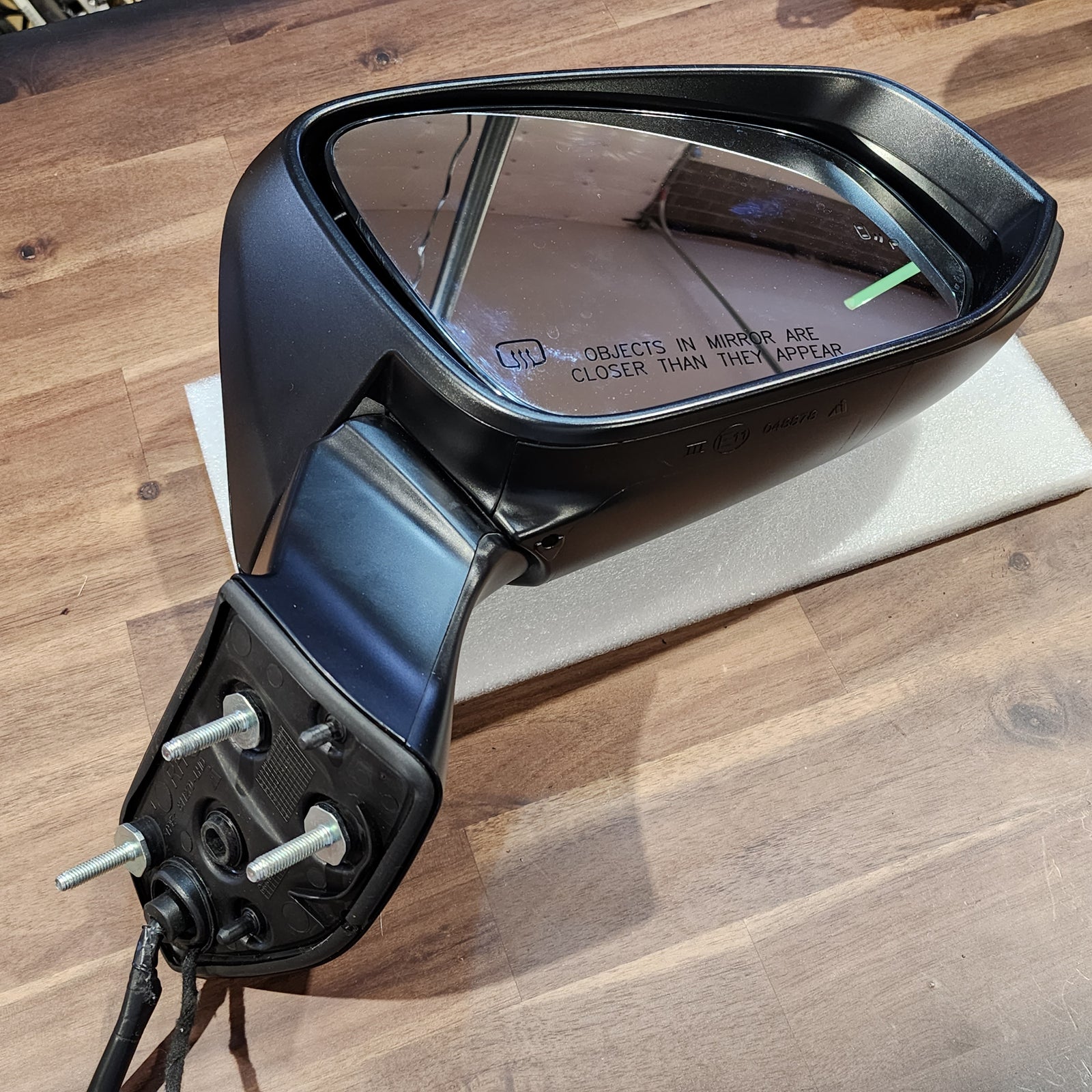
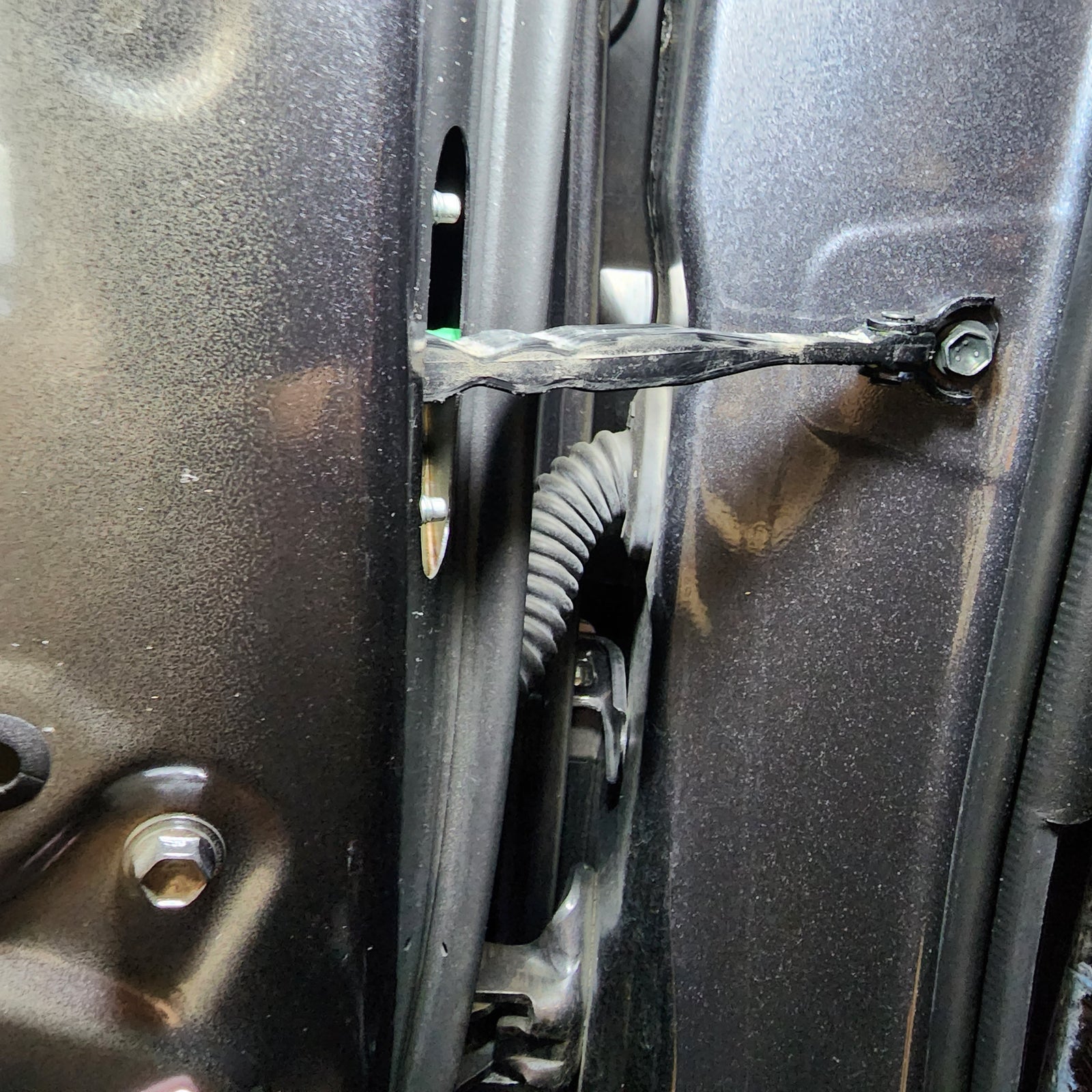
Next, unbolt the mirror assembly by removing the three 10mm nuts that are now exposed. Carefully push back the black plastic tab that’s still holding the mirror in place and pull the whole assembly out, cable and all.
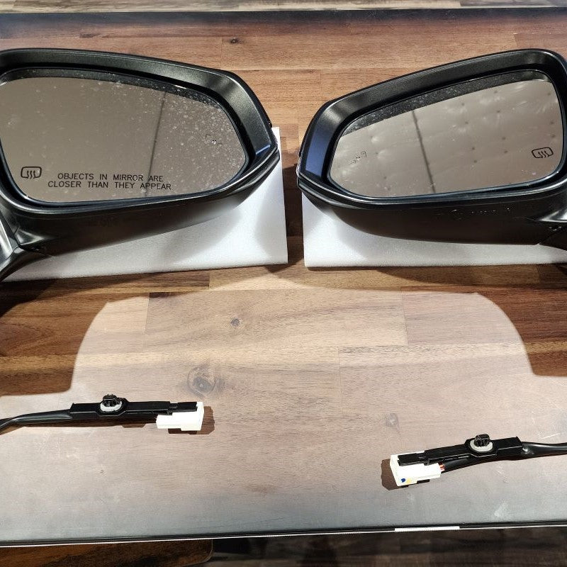
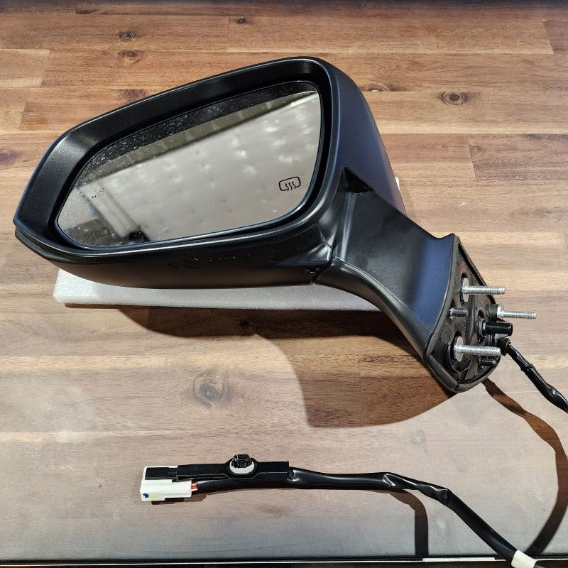
Set the driver side mirror to the side and follow Steps 1-4 for the passenger side mirror as well.
INSTALL IMAGES


STEP 5
-
This is a tricky step.
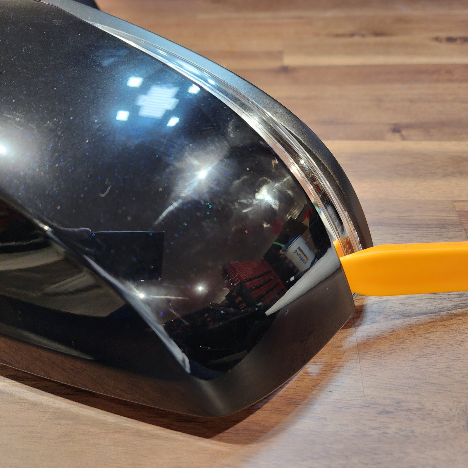
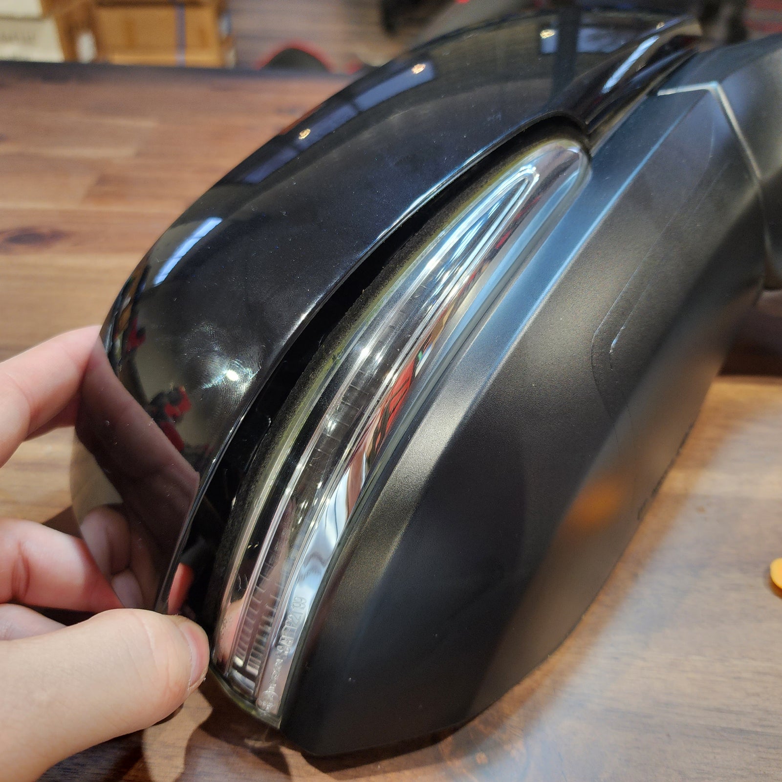
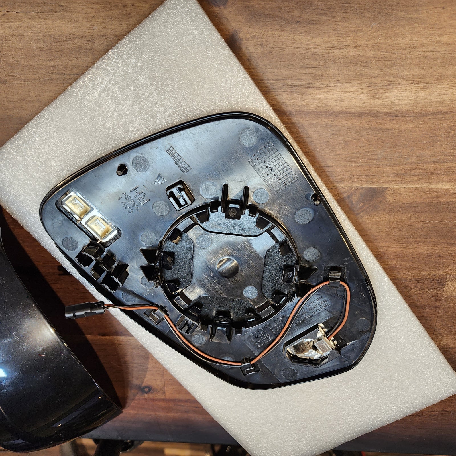
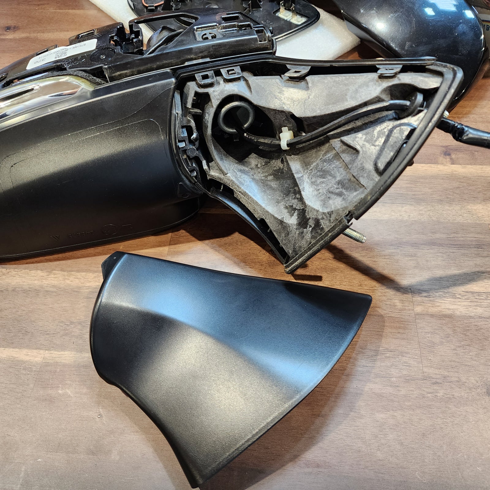
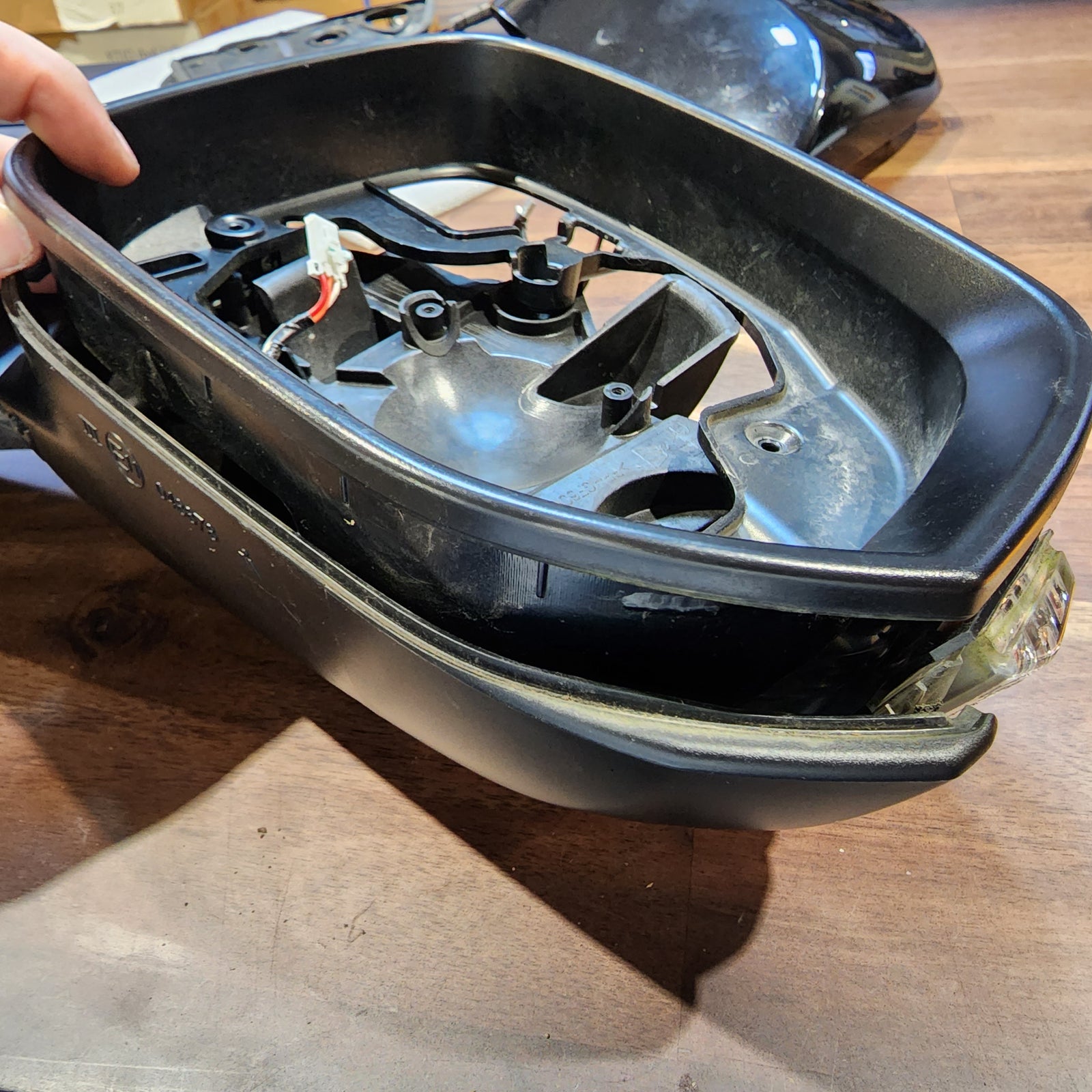
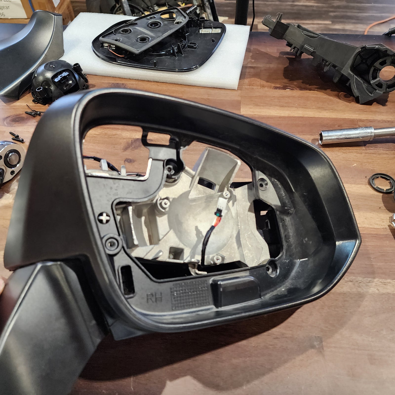
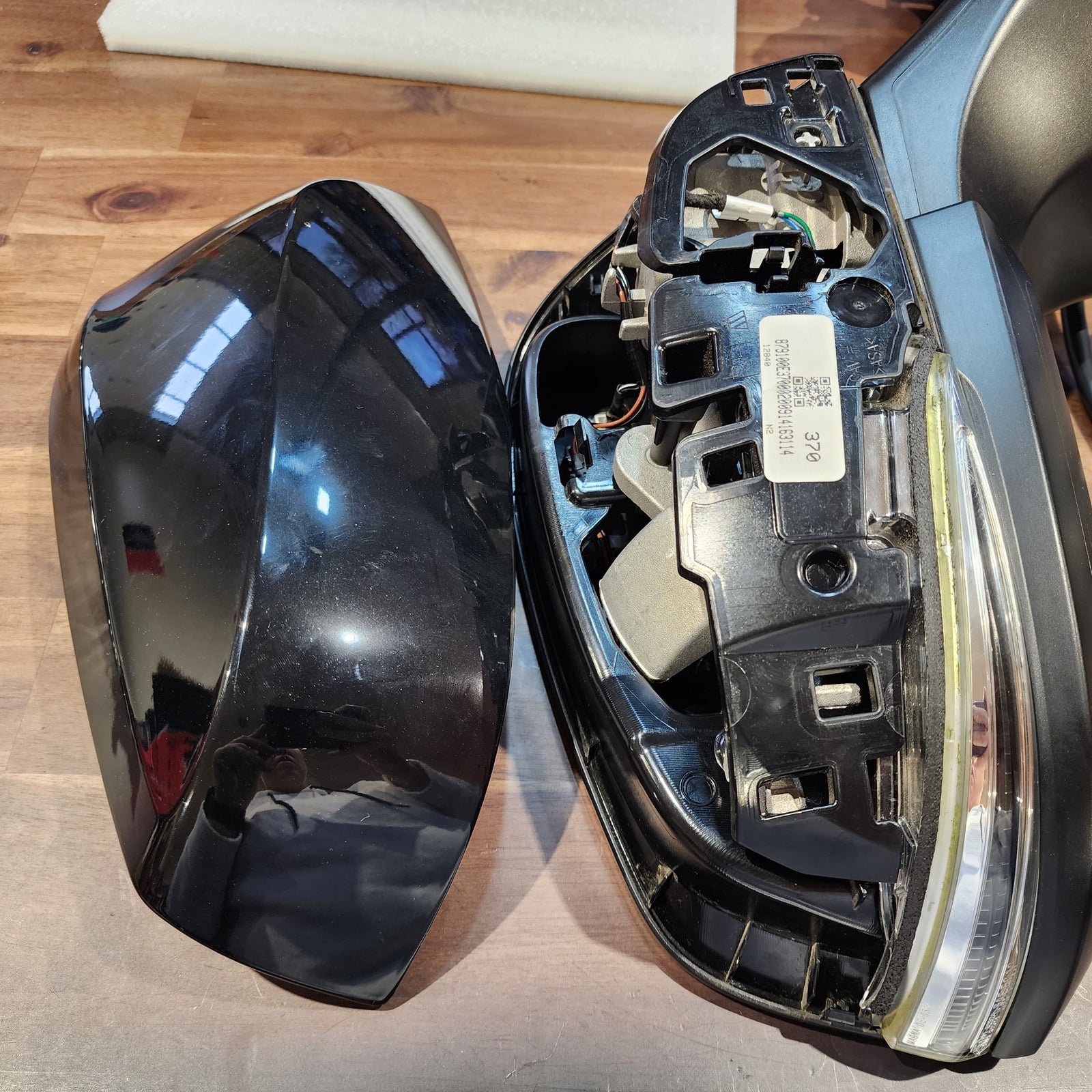
In order to remove your glass mirror from your assembly, depending on your factory mirror, you may need to grab your trim removal tool and put it on the bottom portion of the mirror and lift up. Some models you will need to just reach in on the top of the glass and pull it out.
Now, grab a small flat head screw driver and look closely at the full connector, you’ll notice a small tab that is holding the mirror on the back. This needs to be pulled up to release the connector.
Last part of disassembling the glass, be careful that you do not damage the back side of your mirror in the process as sometimes it can be difficult to disconnect the two-pin connector for the mirror defroster away from the upper right corner. If you would like to mark the top wire with some tape for reassembly, now is the time to do so as both of these wires are black. It will make reassembly much easier in the end rather than trying to remember which one went where.
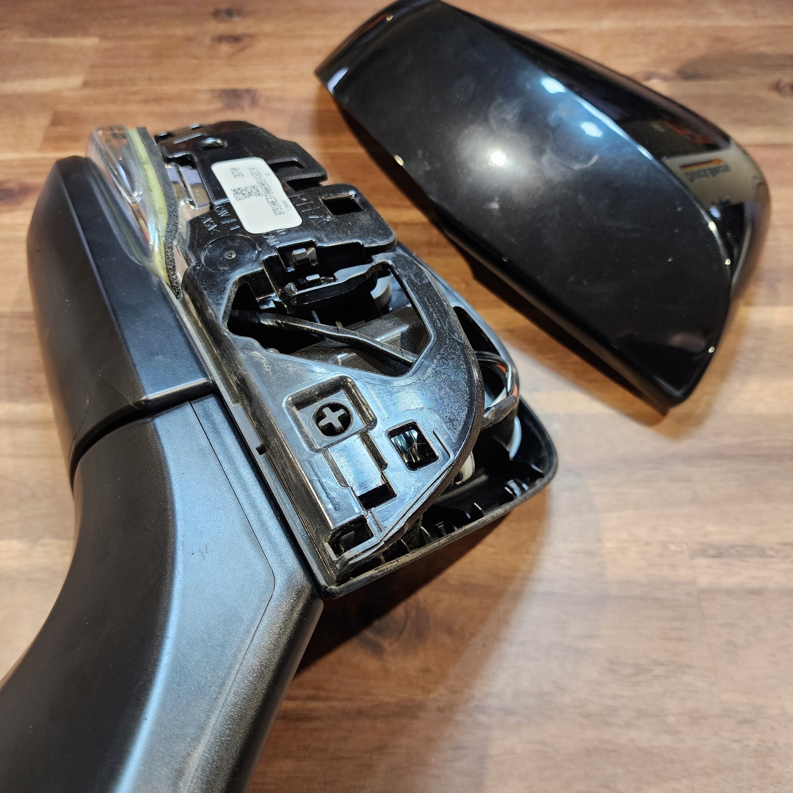
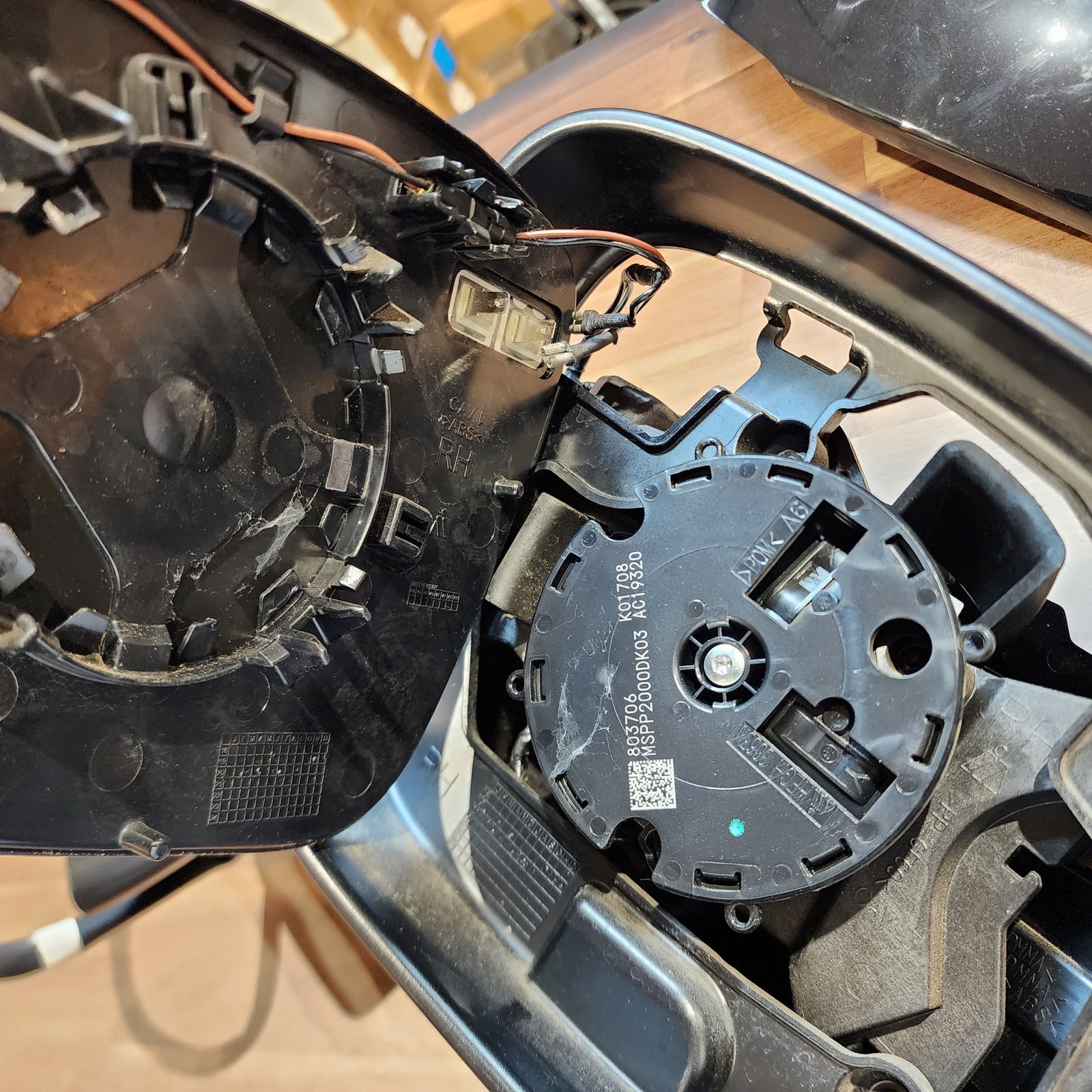
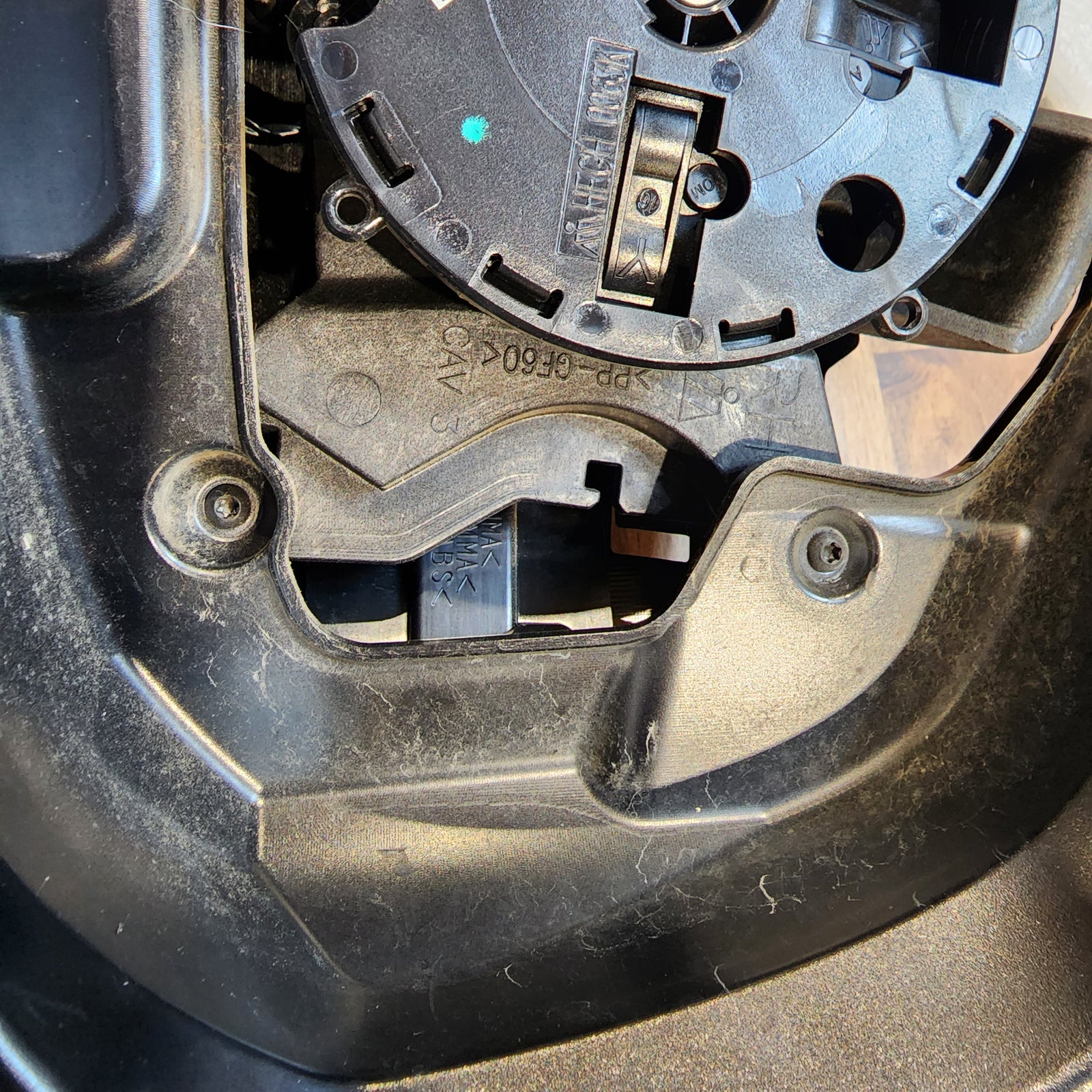
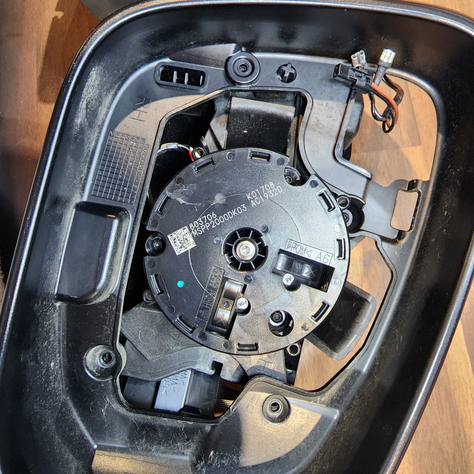
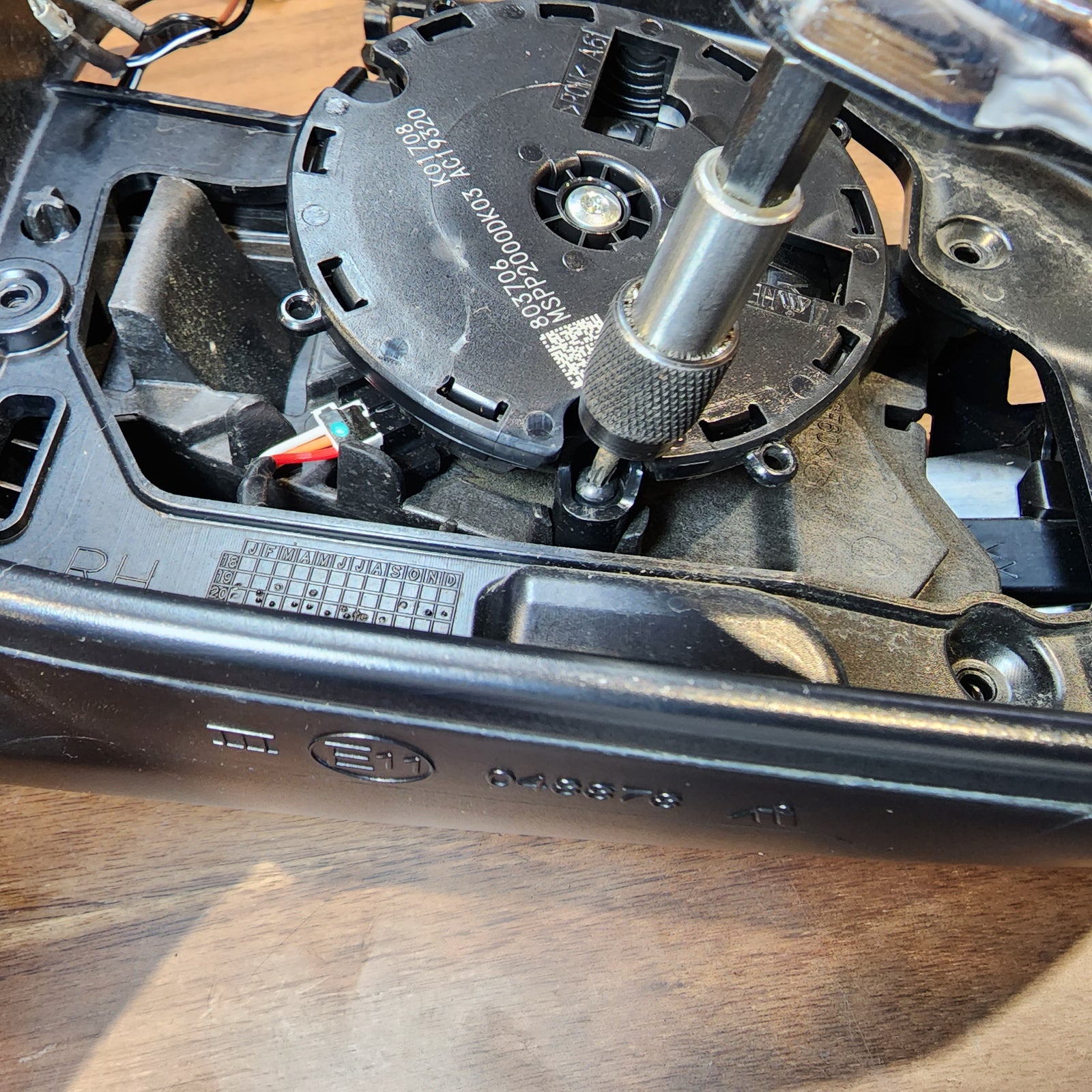
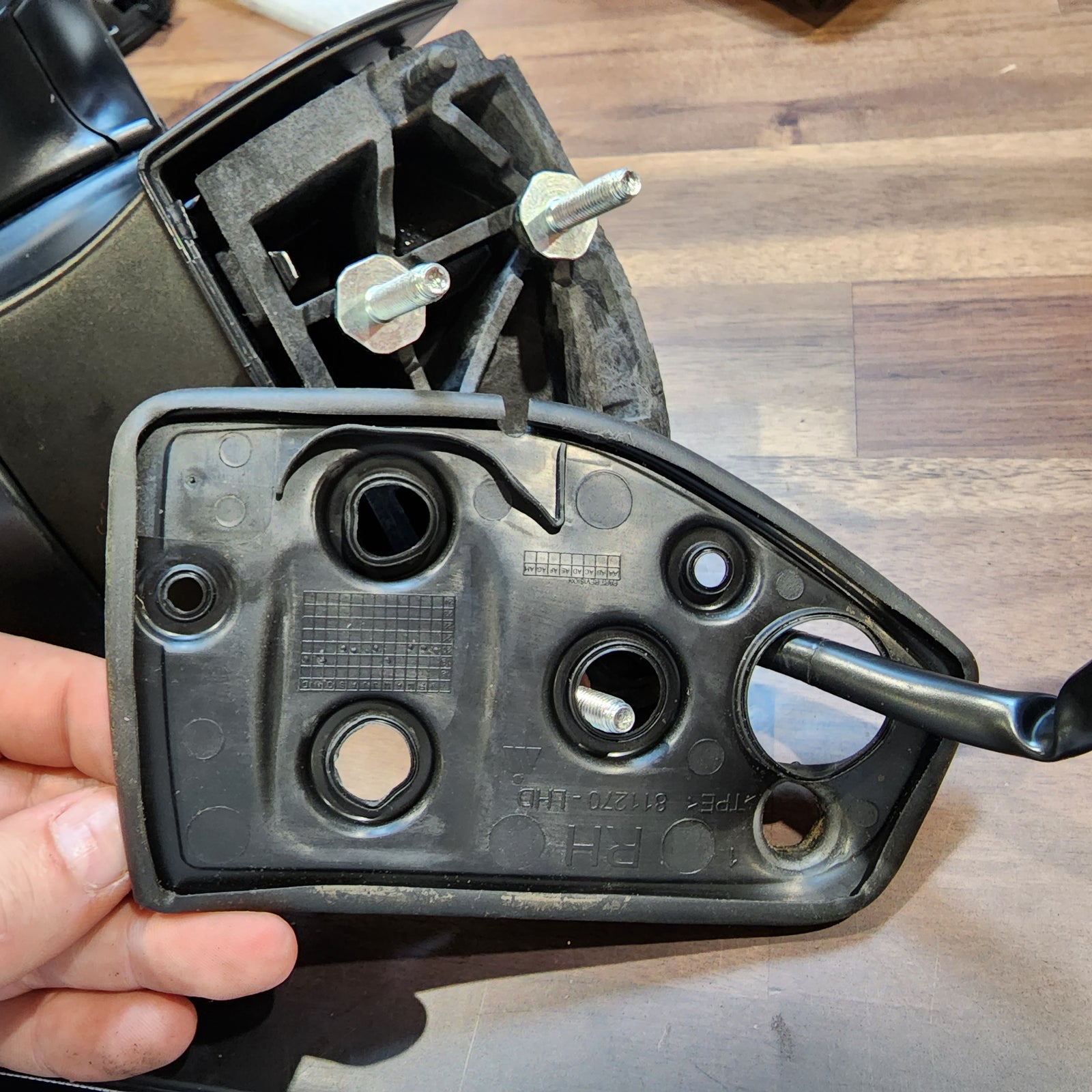
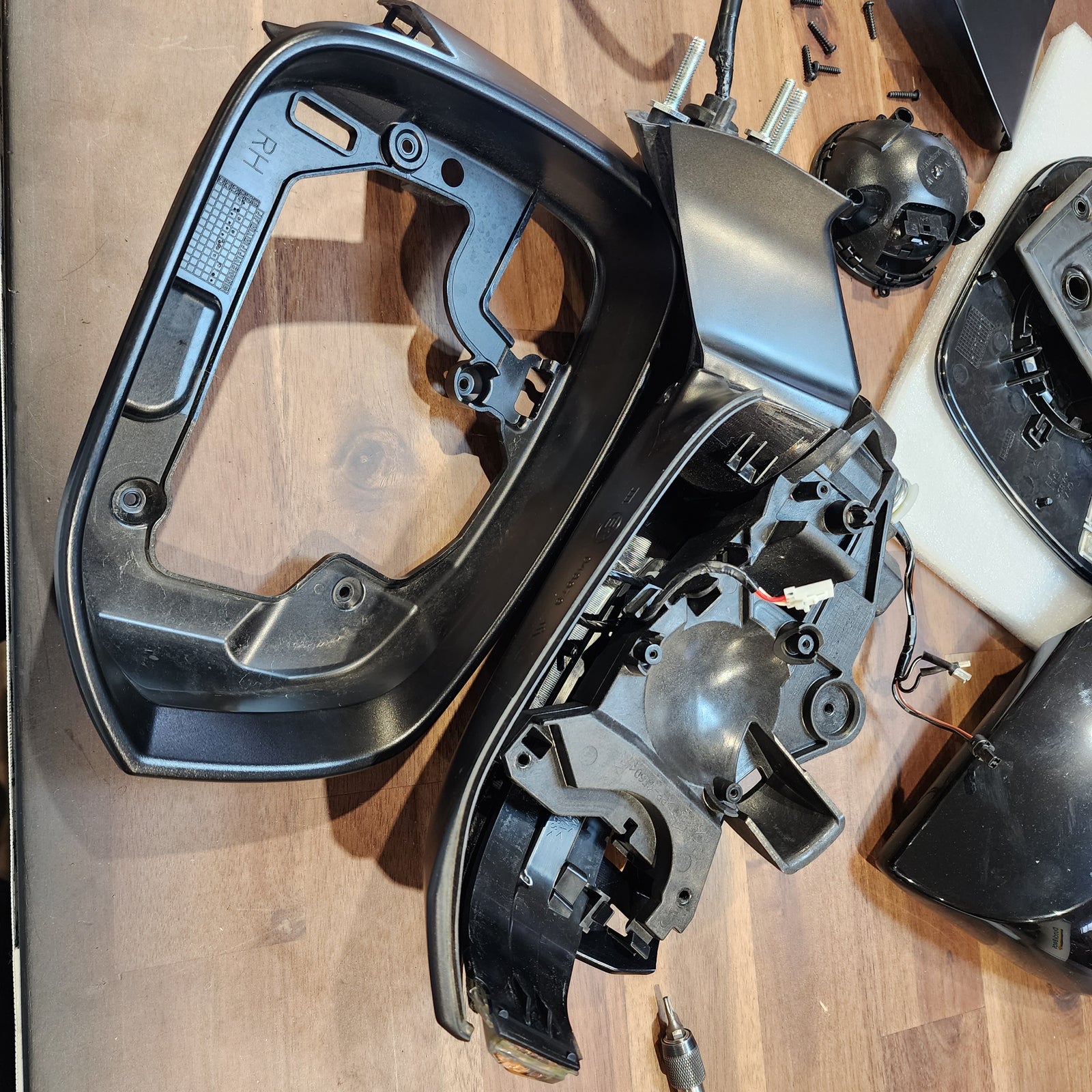
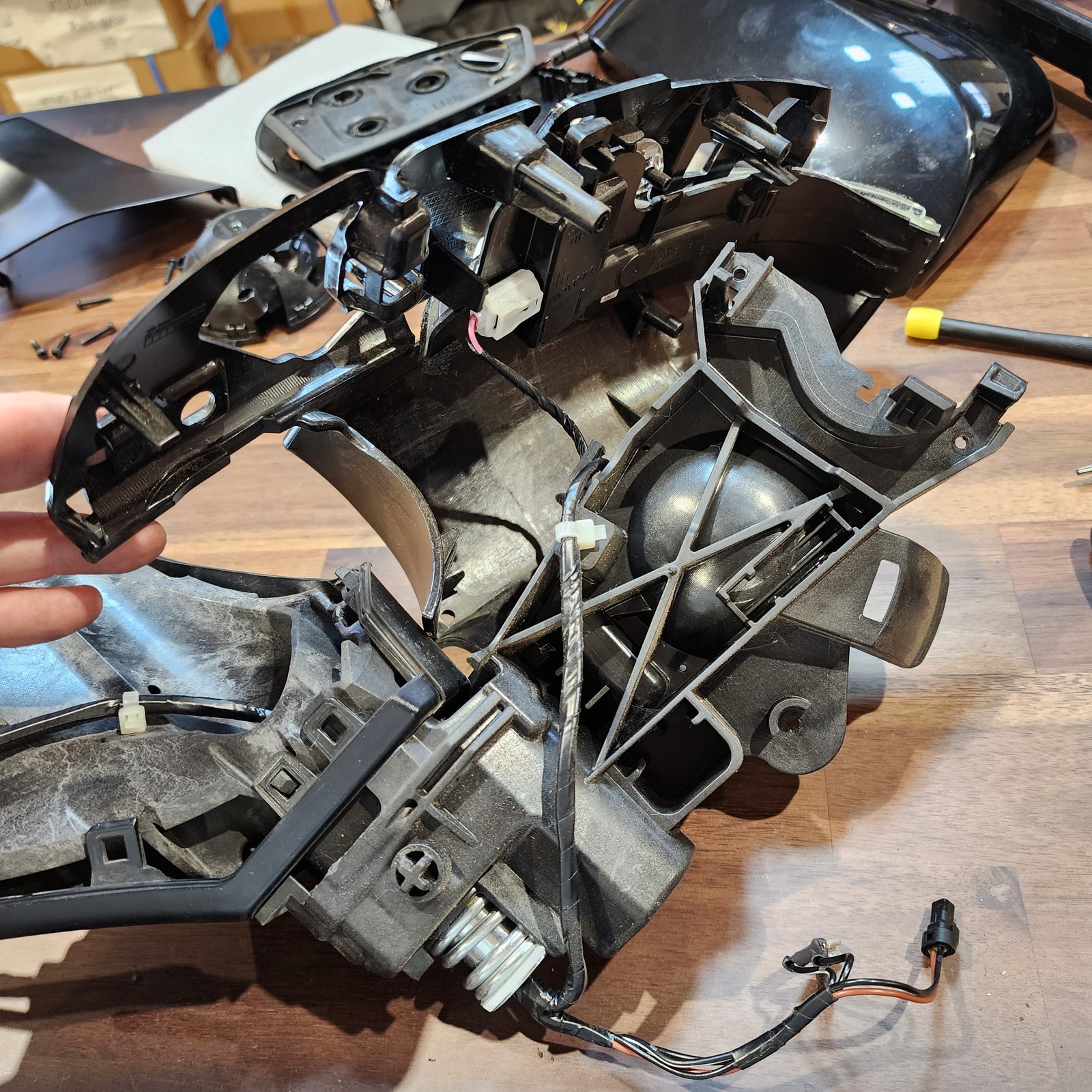
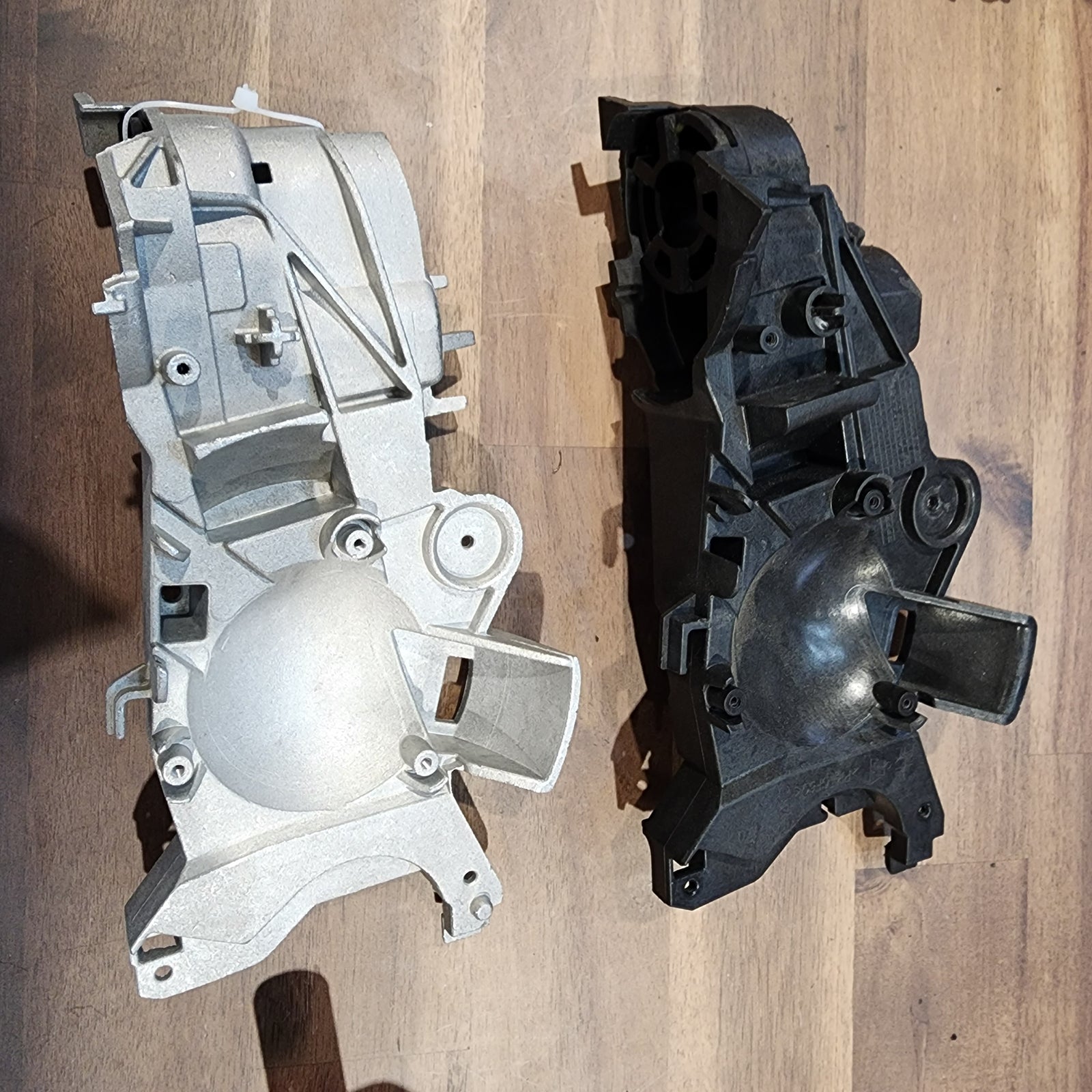
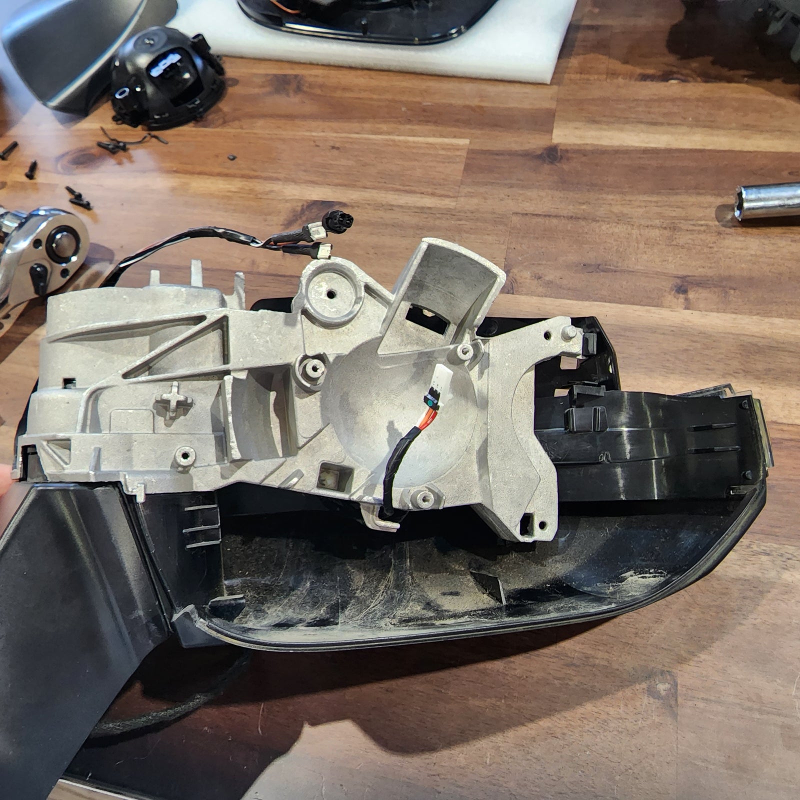
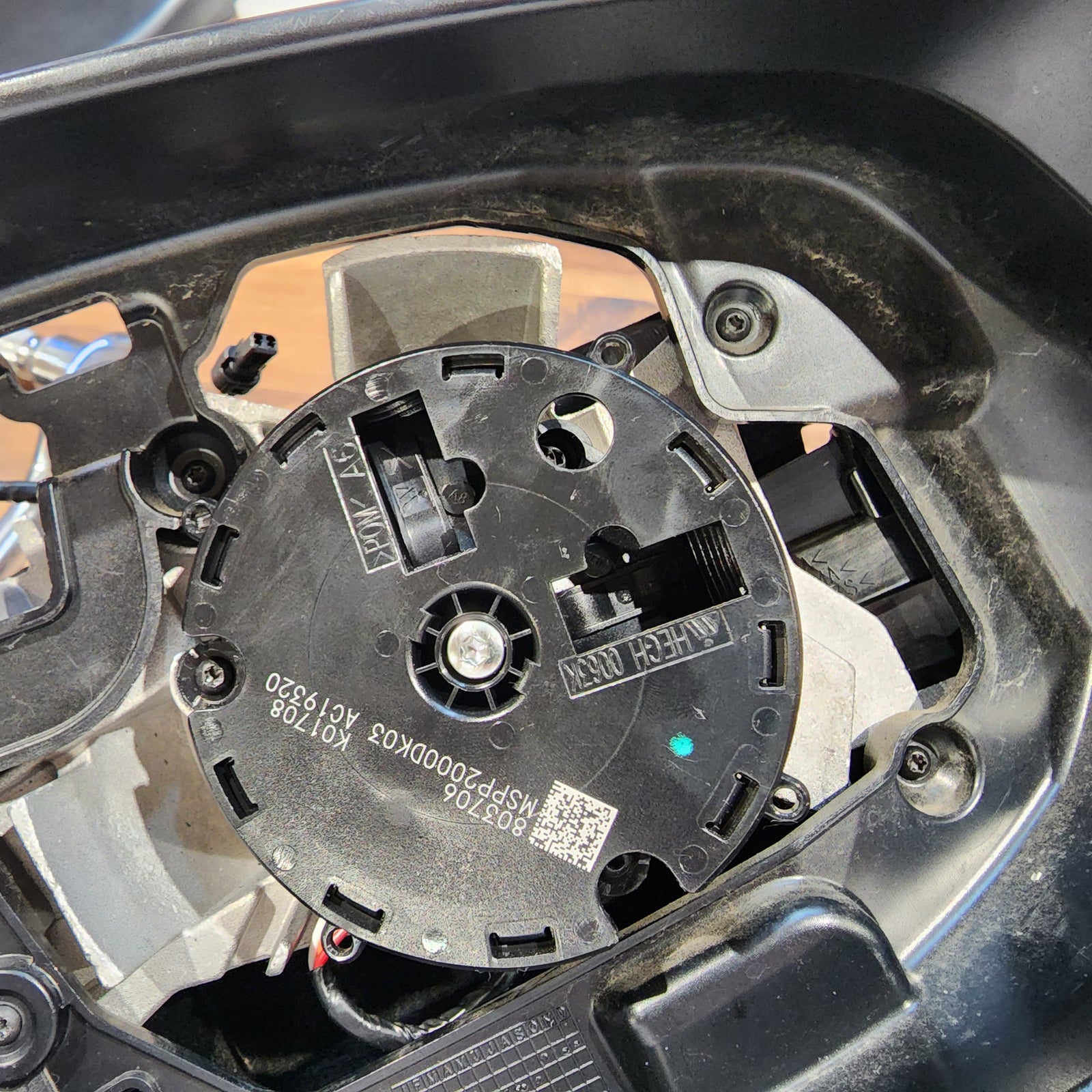
Next, using a T15 Torx Screwdriver, remove the 3 screws that are securing the directional actuator motor to the inner connection plate. At this time you can also remove the 3 screws that are securing the mirror outer housing to the inner connection plate.
Just a little reminder, as you disassemble these parts, make notes if you need to for later. Set these parts aside for the end.
INSTALL IMAGES


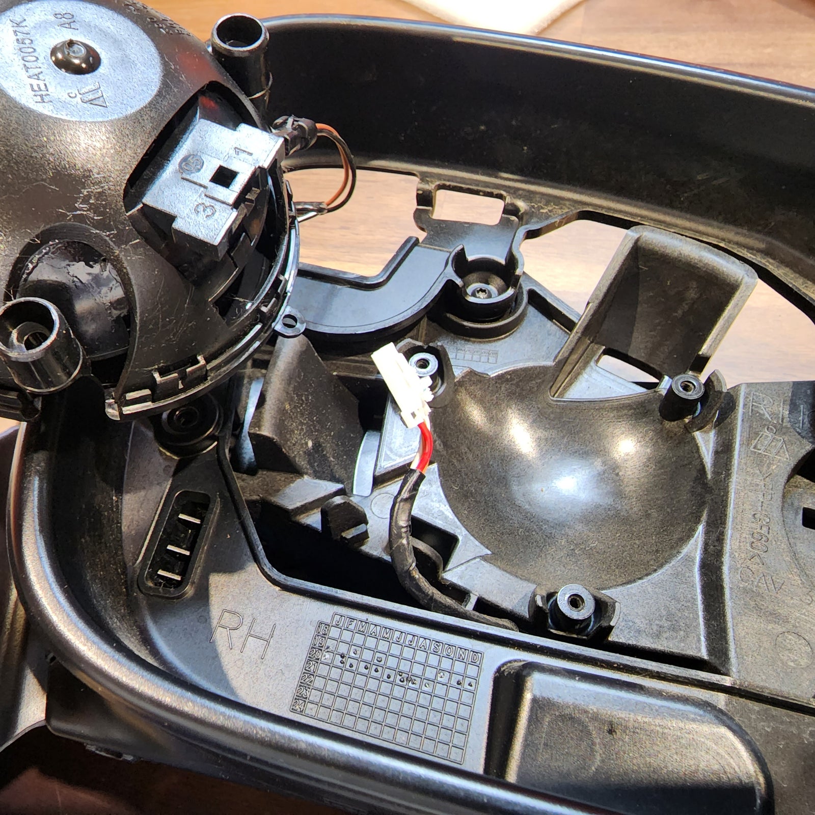

STEP 6
-
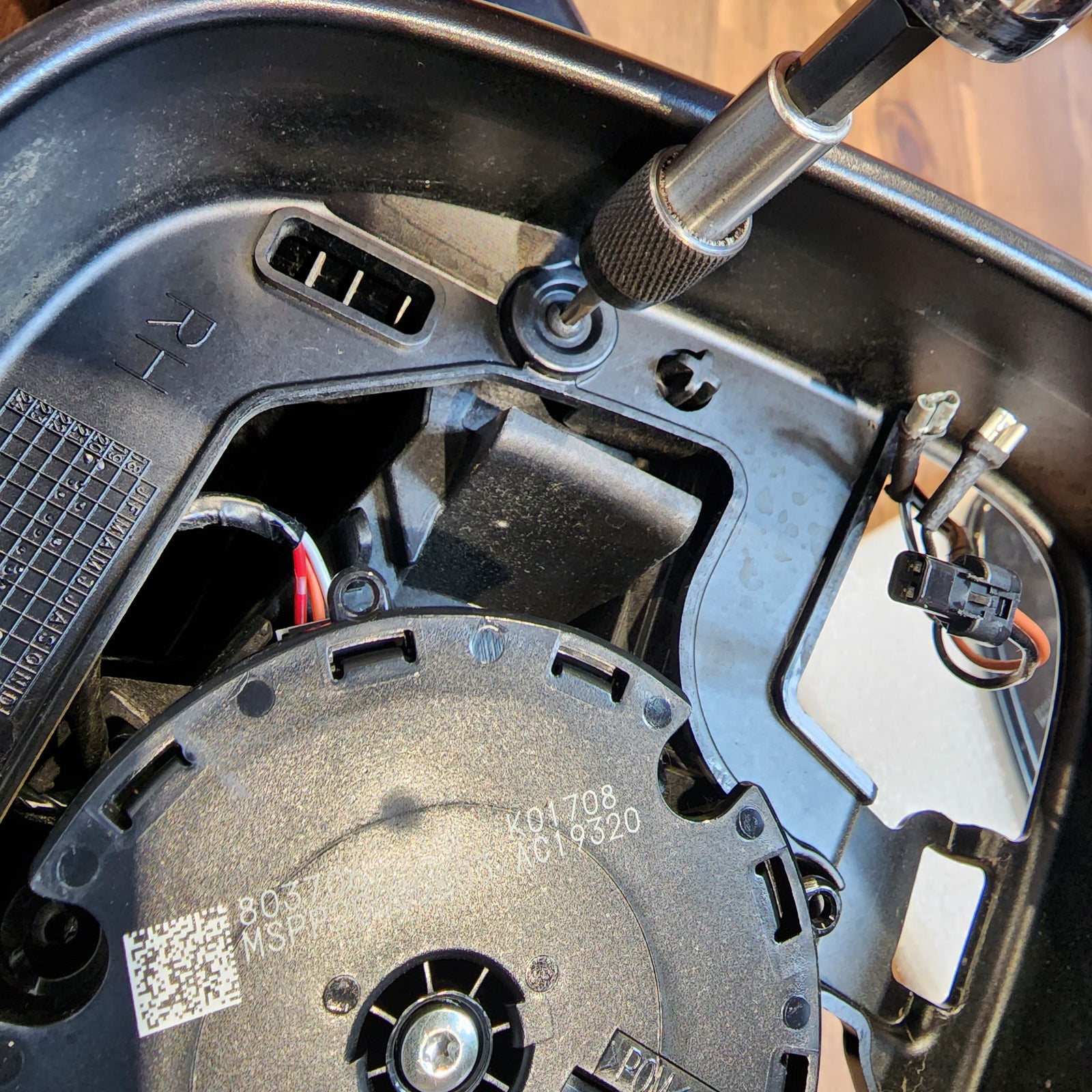
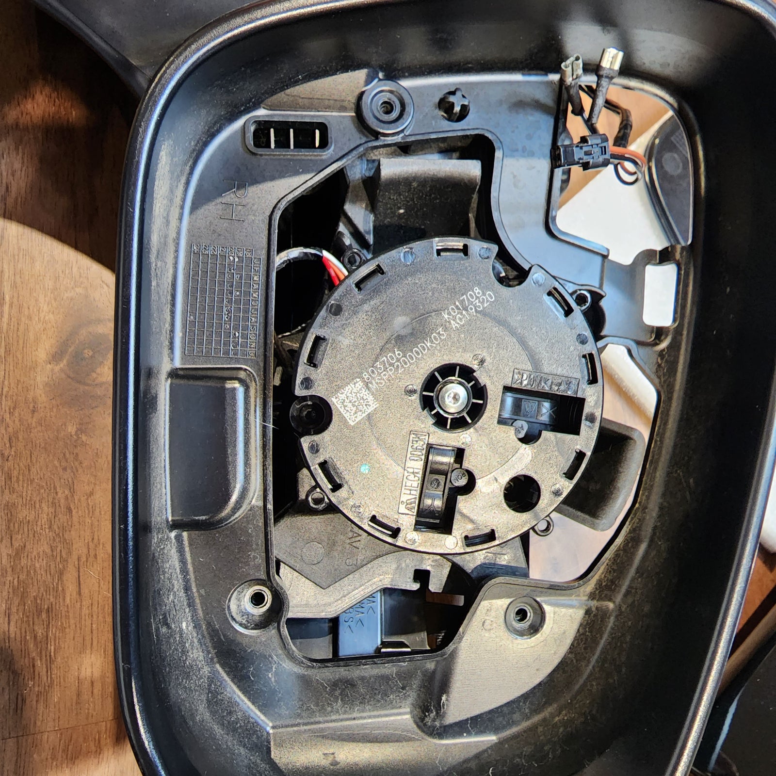
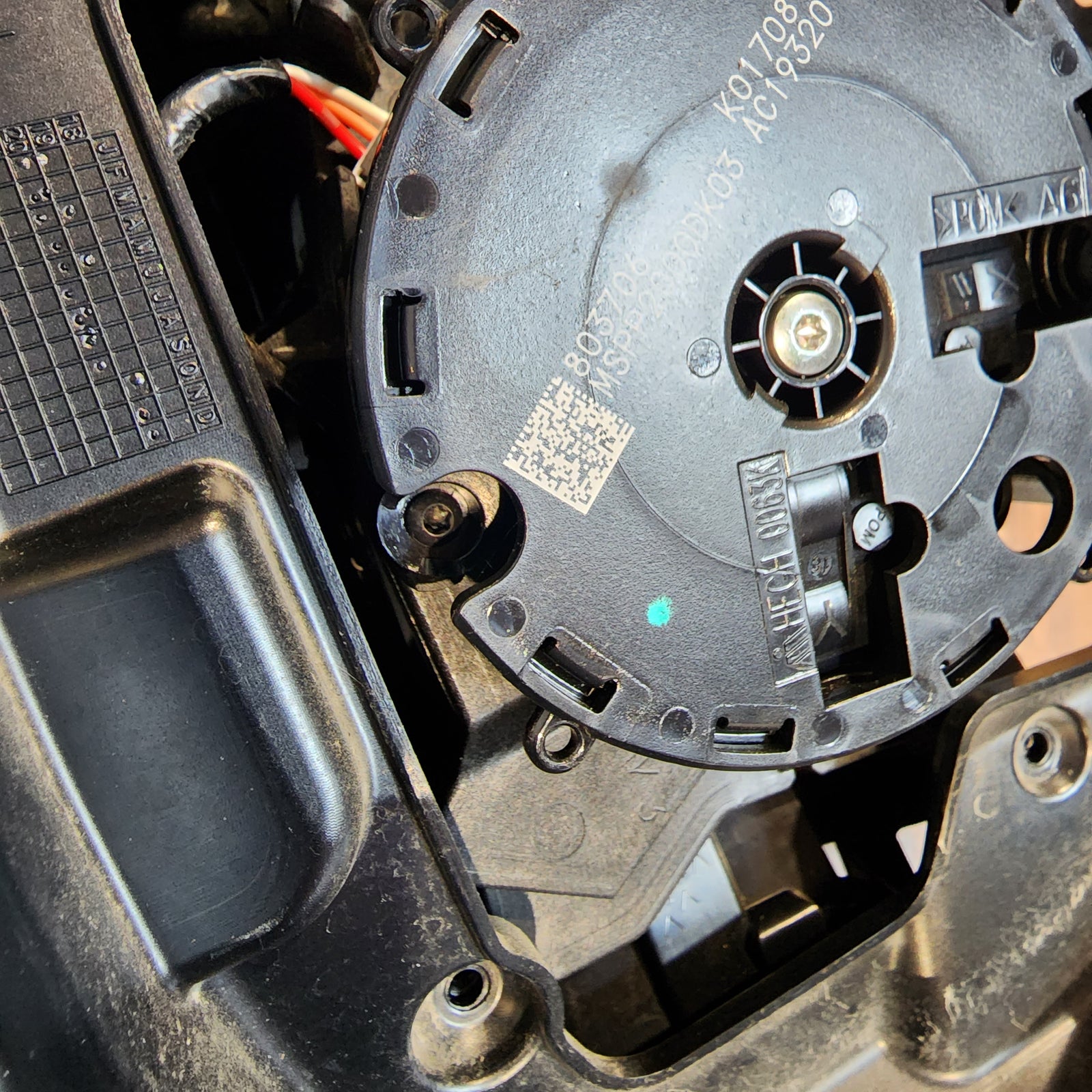
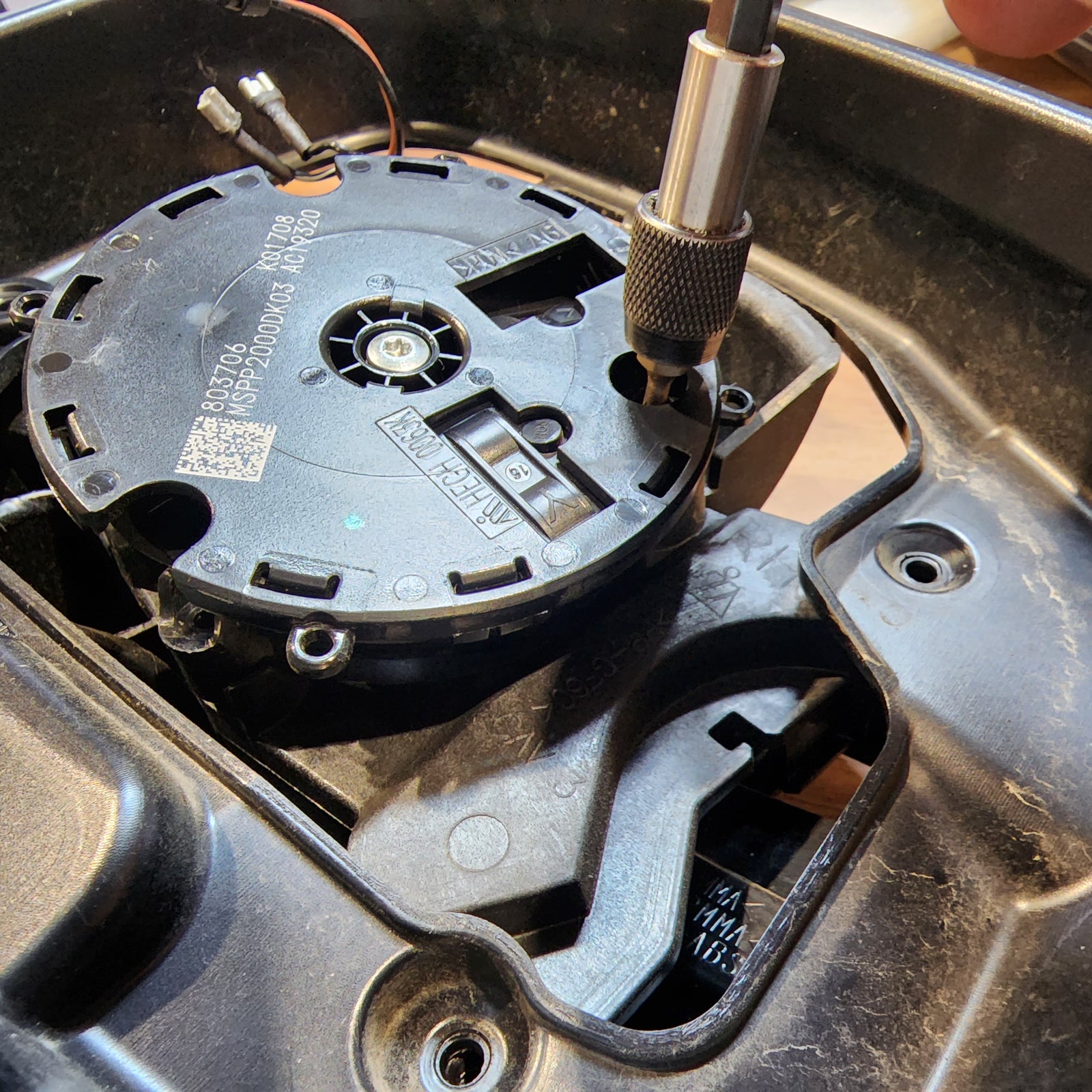
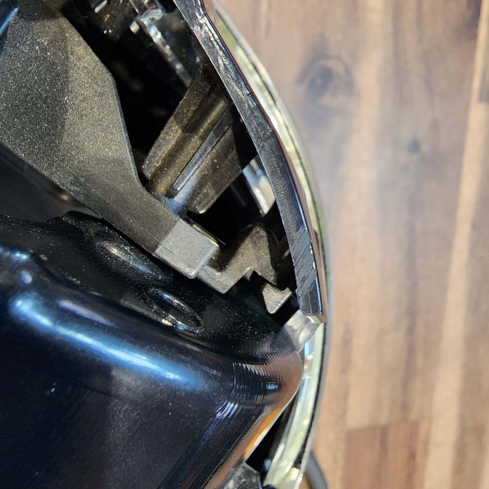
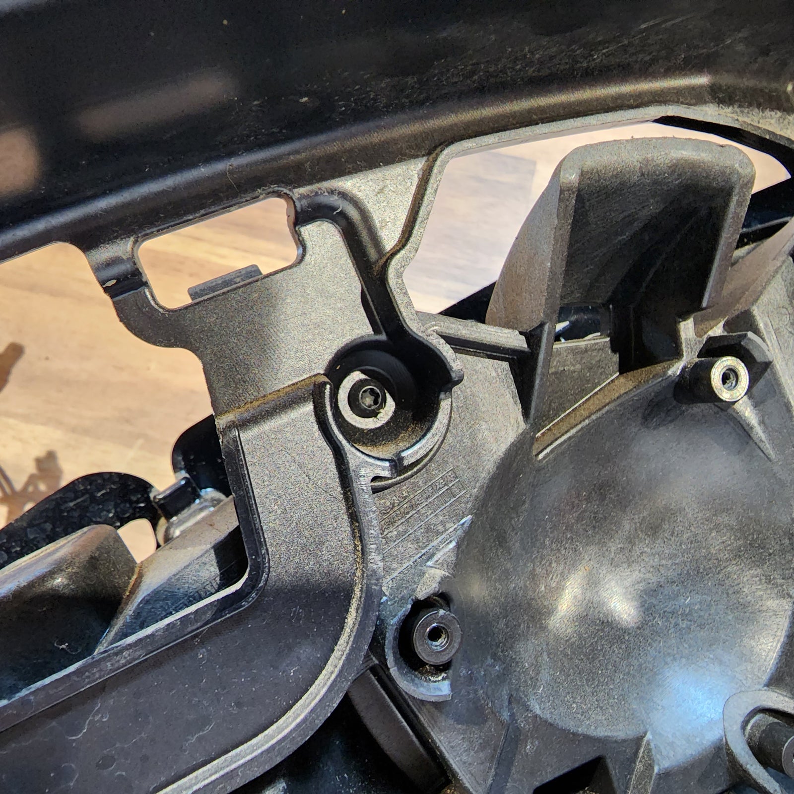
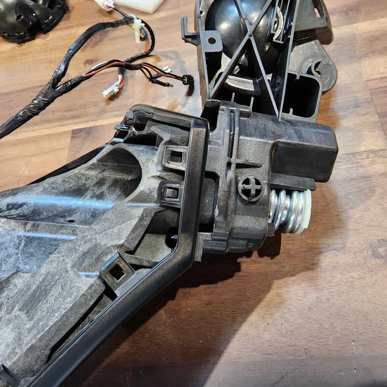
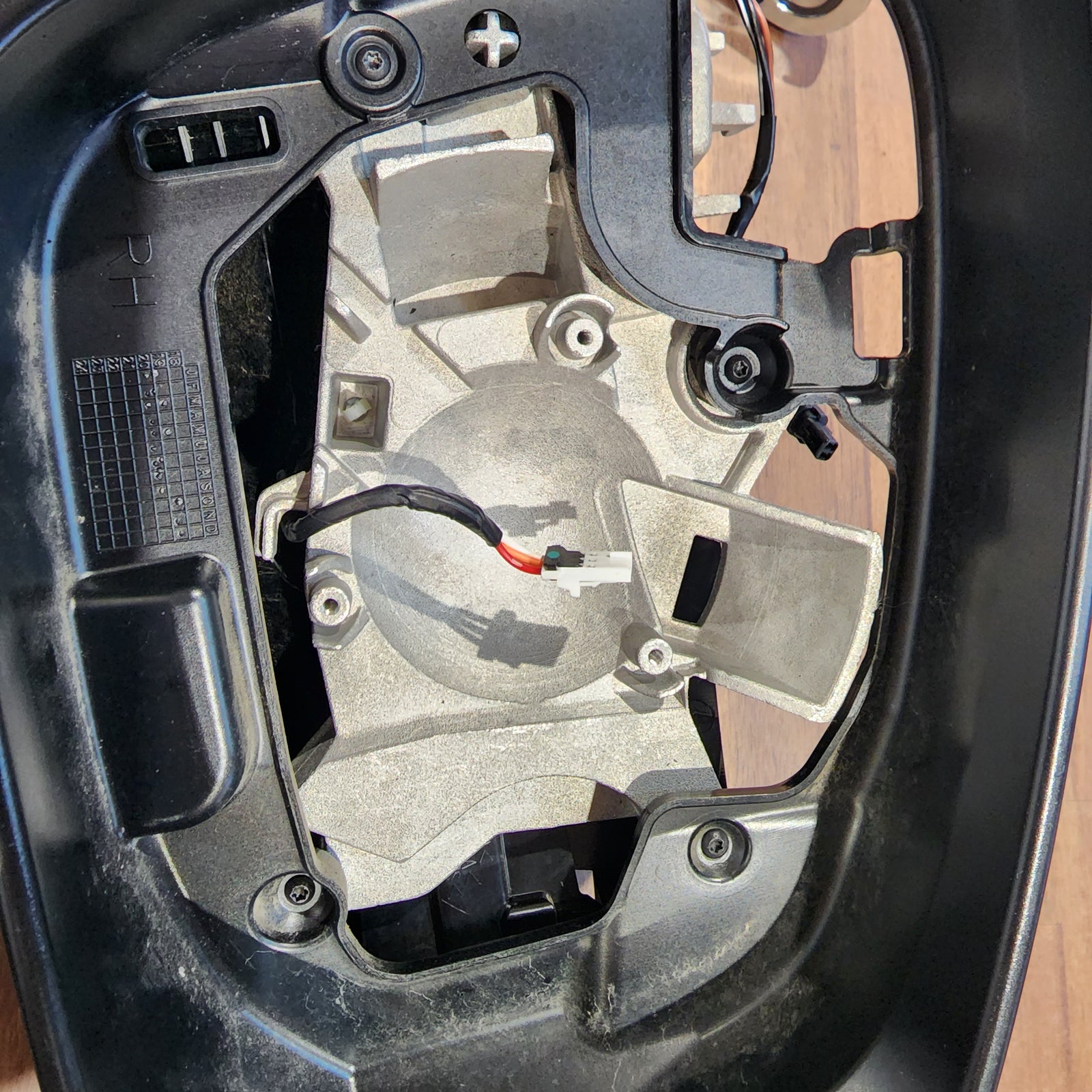
Continuing to use a T15 Torx Screwdriver, remove the any screws that are securing the connection plate to the mirror housing that may be visible with the actuator removed at this time. Set all hardware that you remove to the side for future reinstallation.
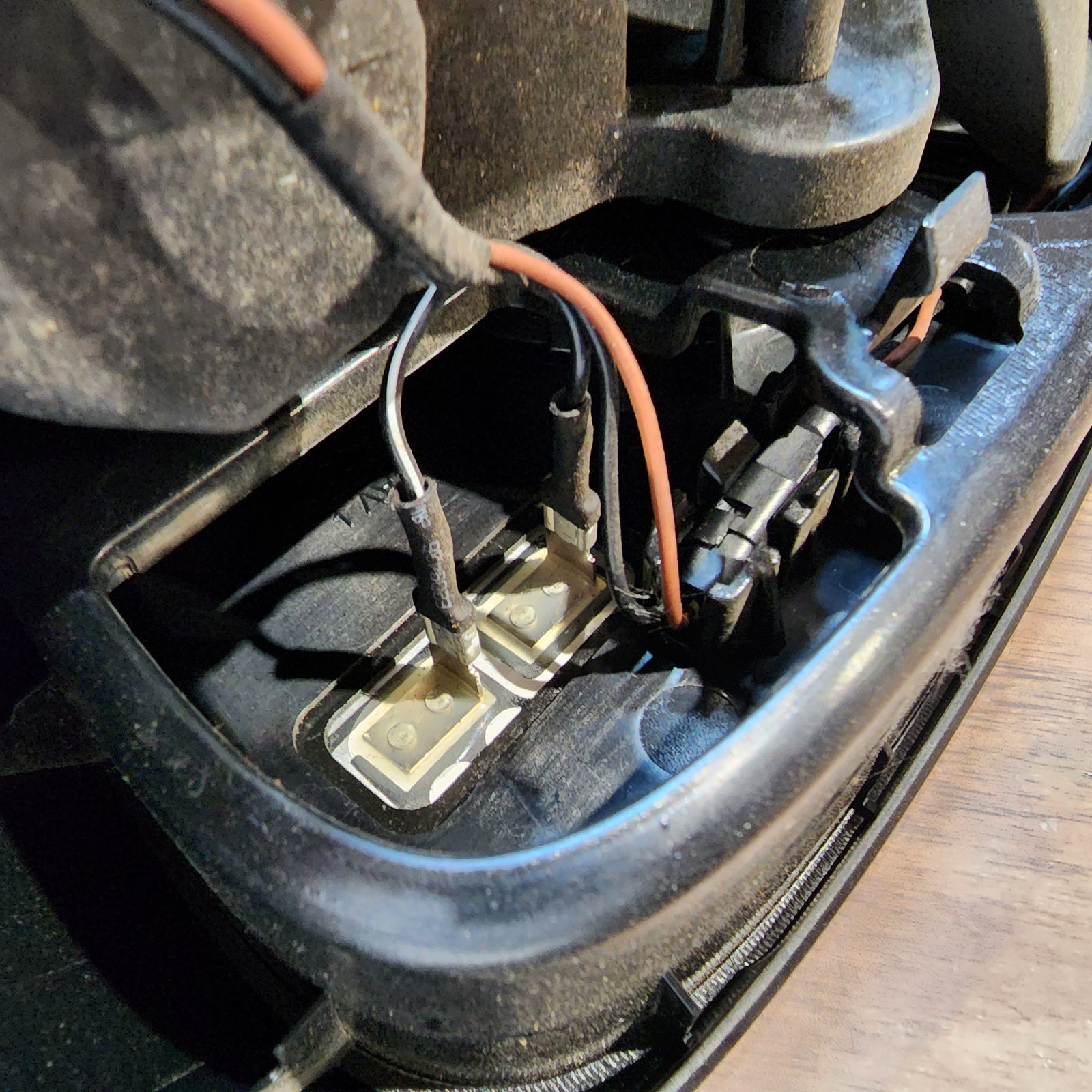
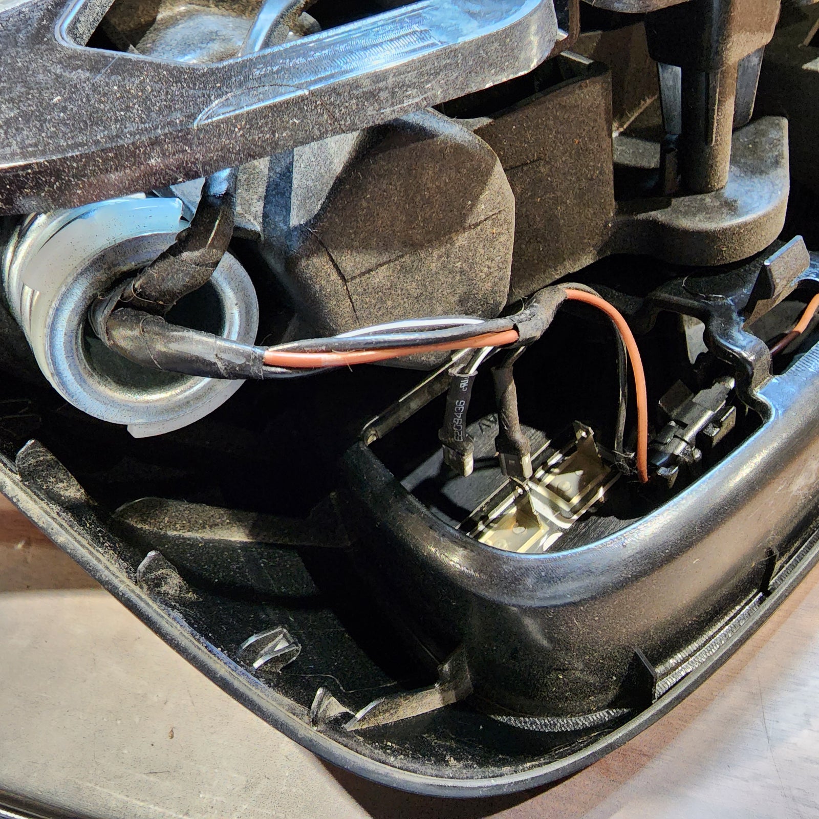
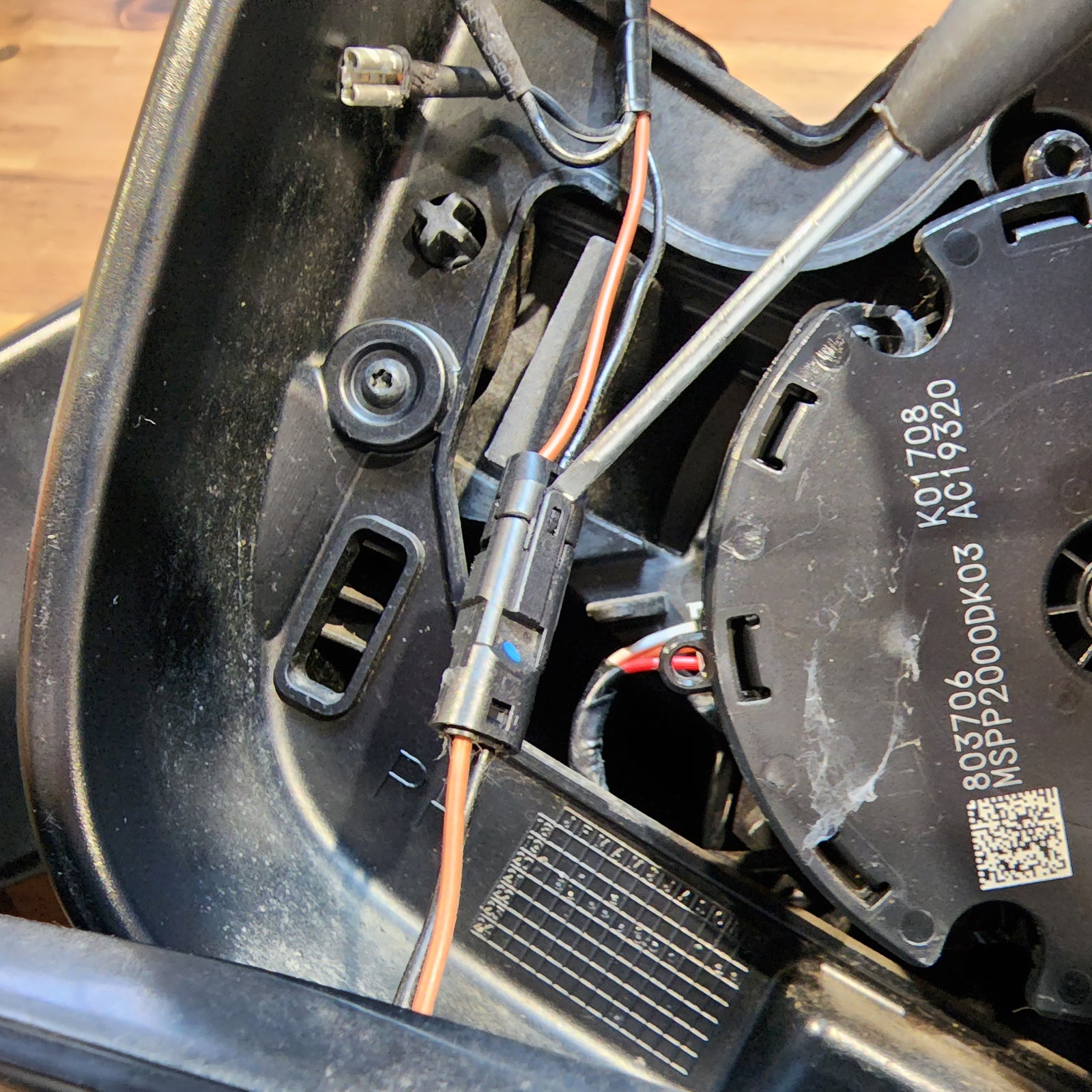
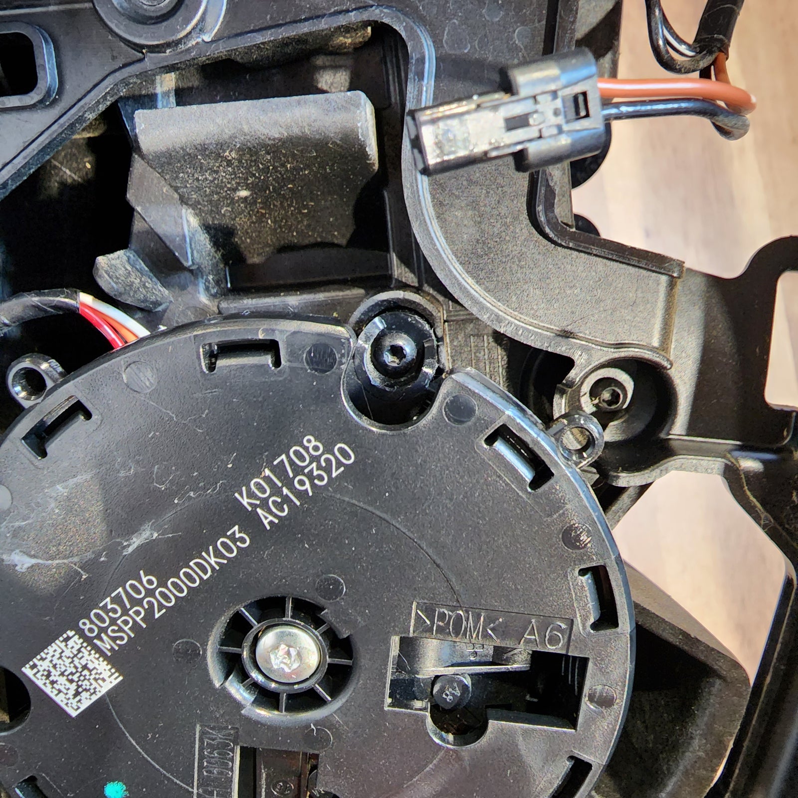
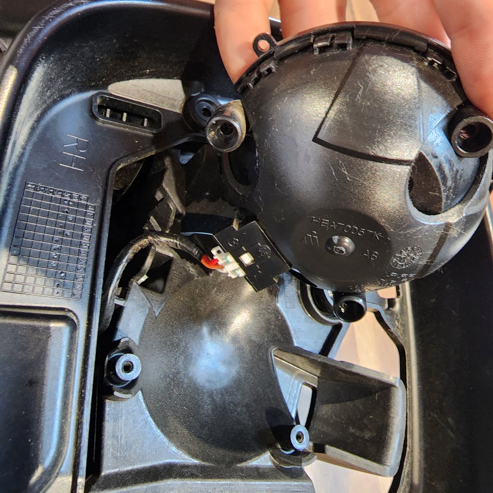
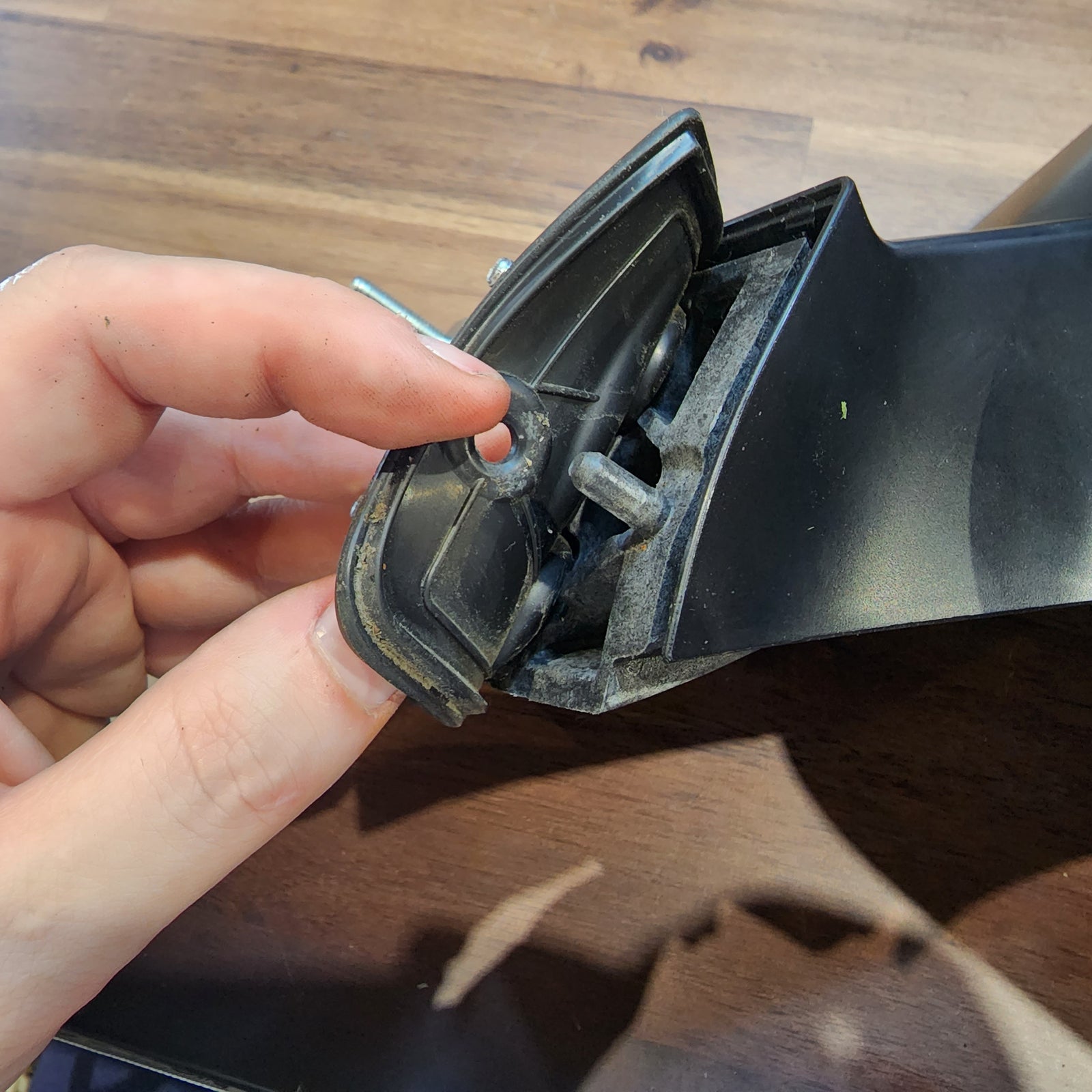
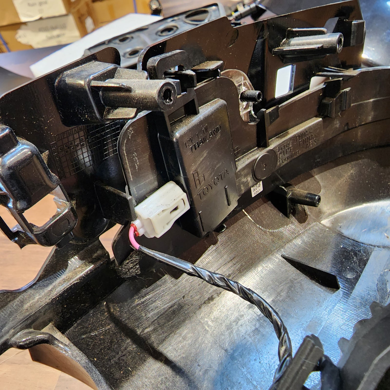
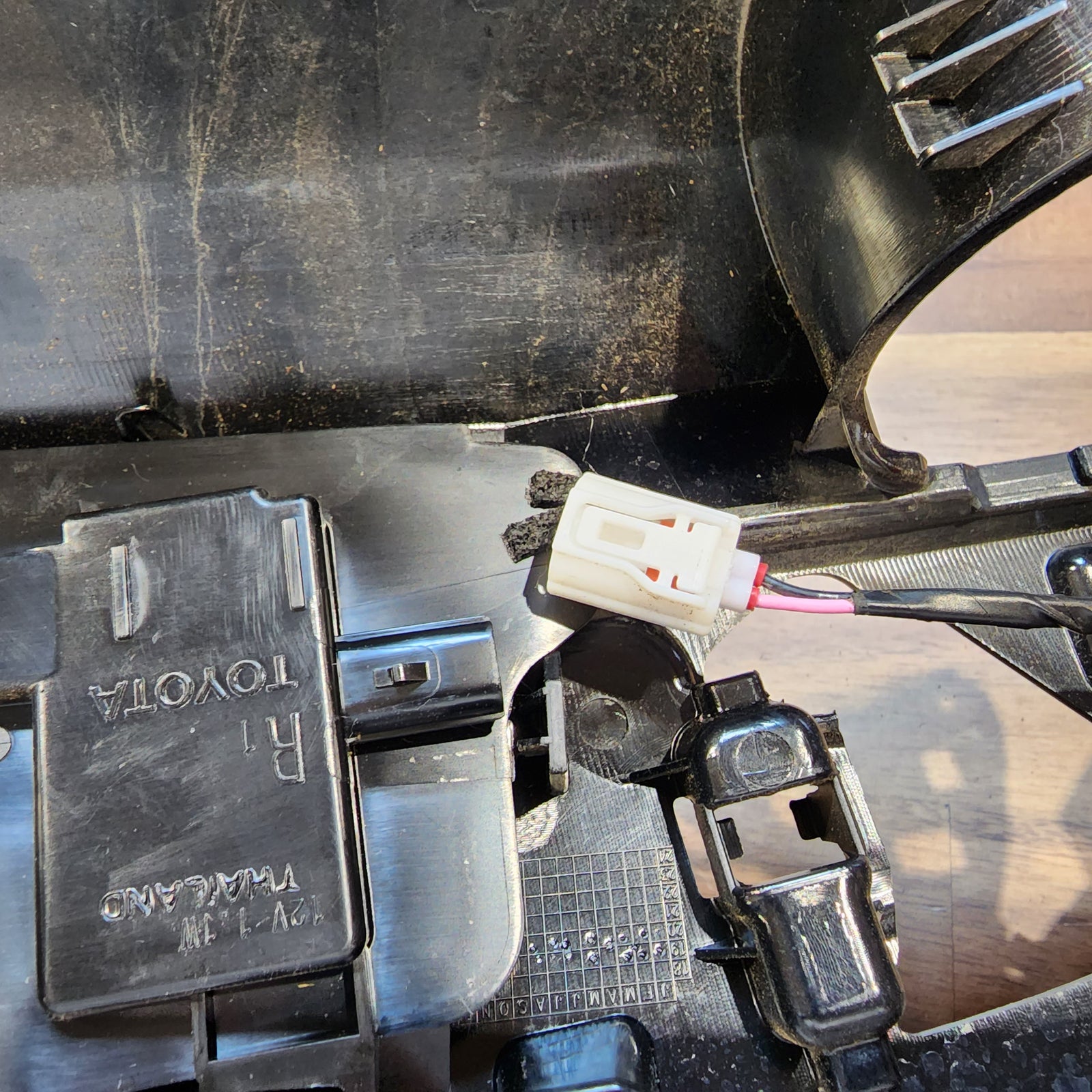
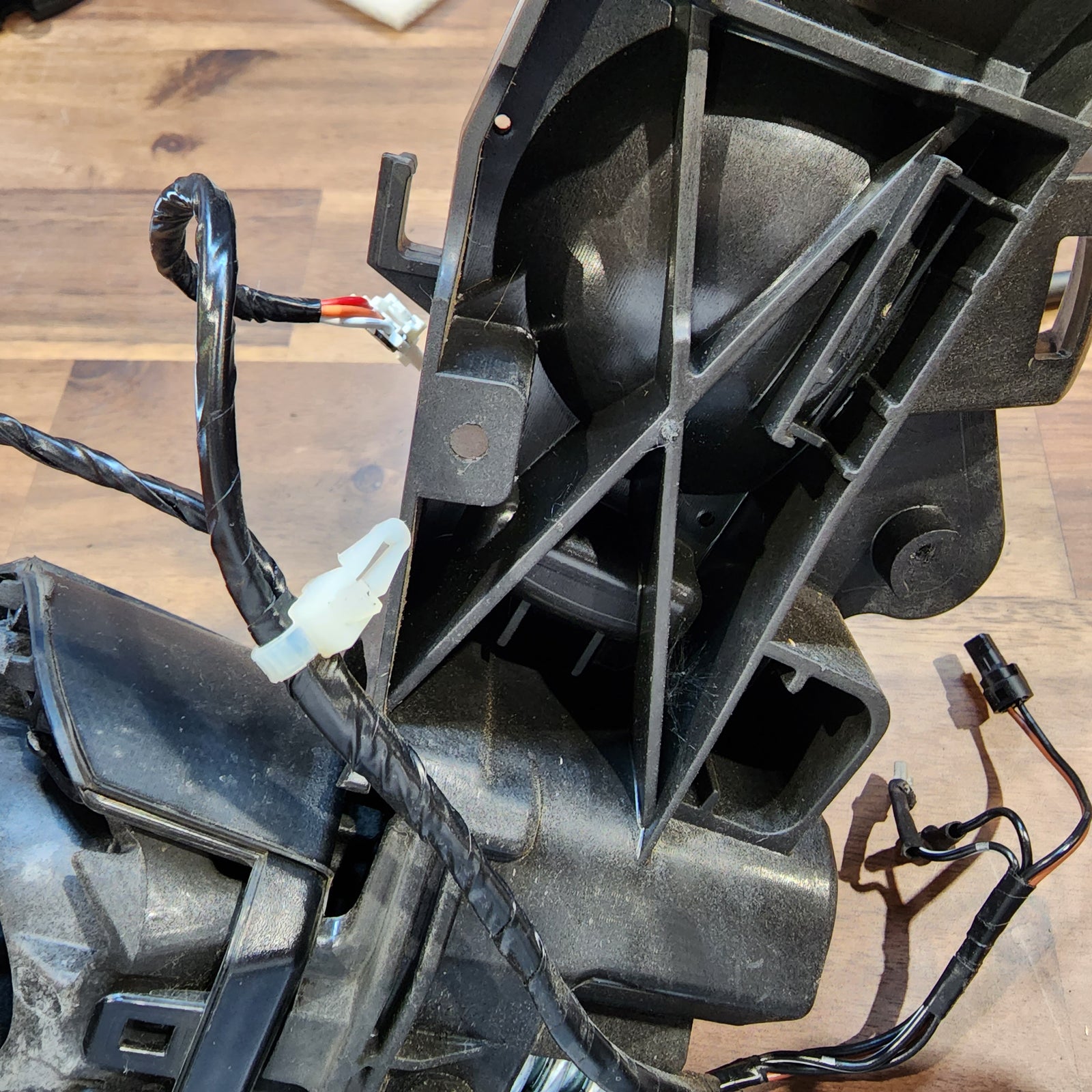
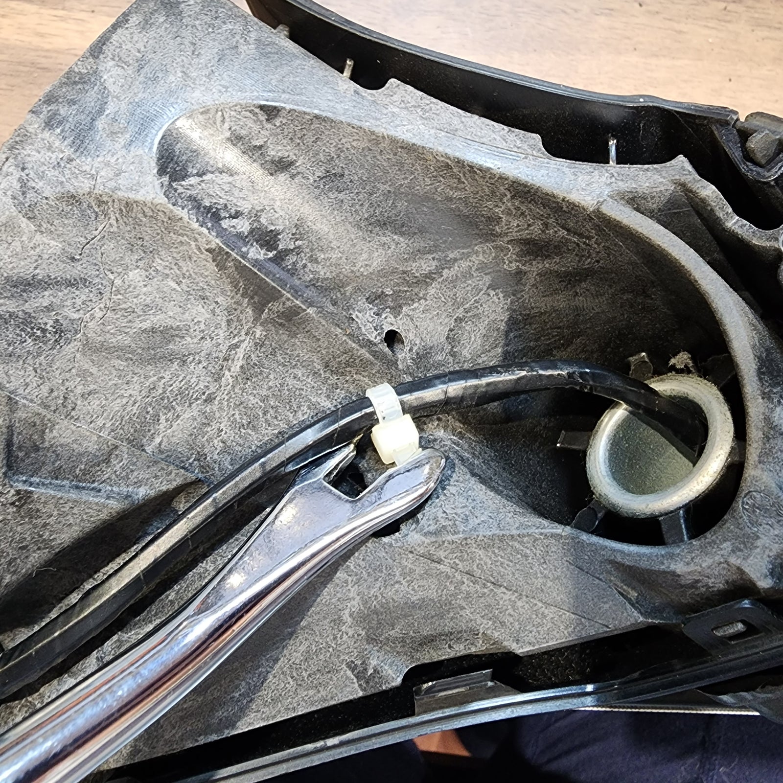
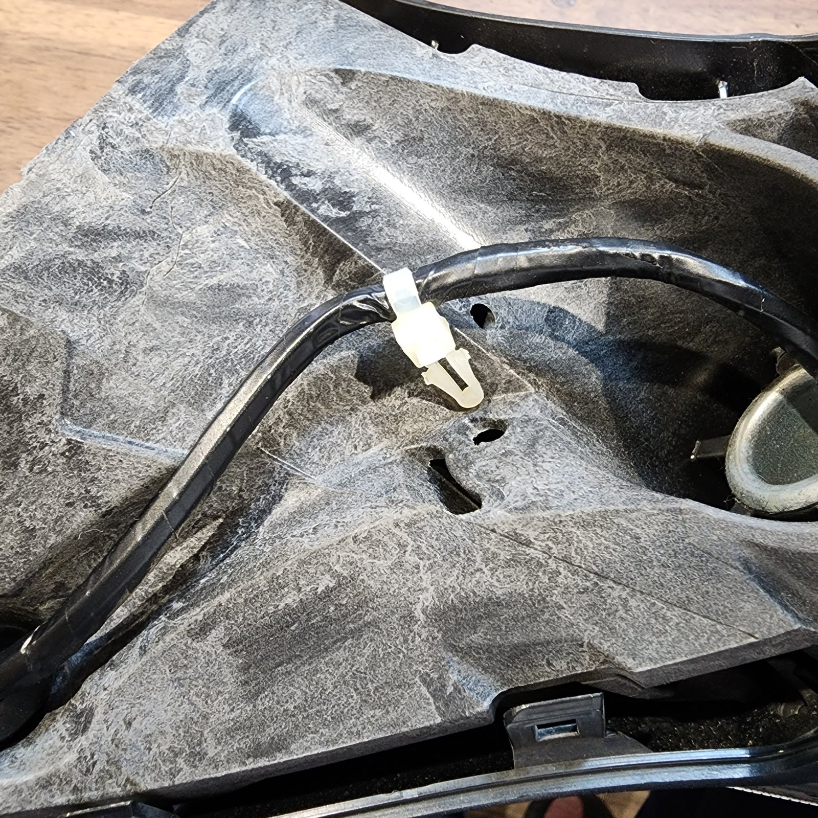
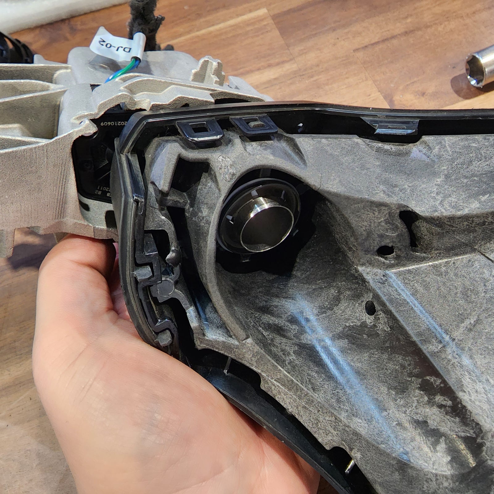
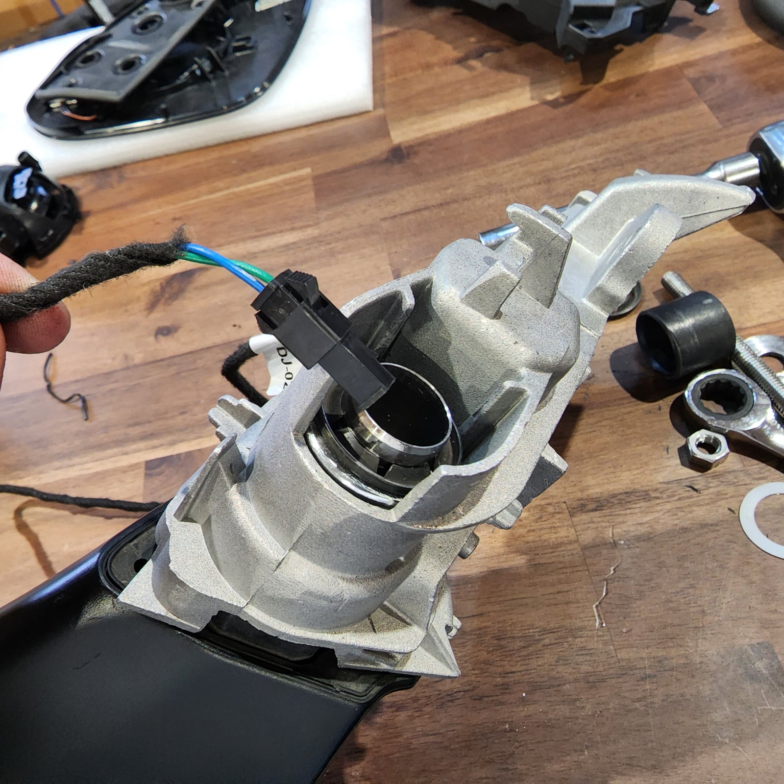
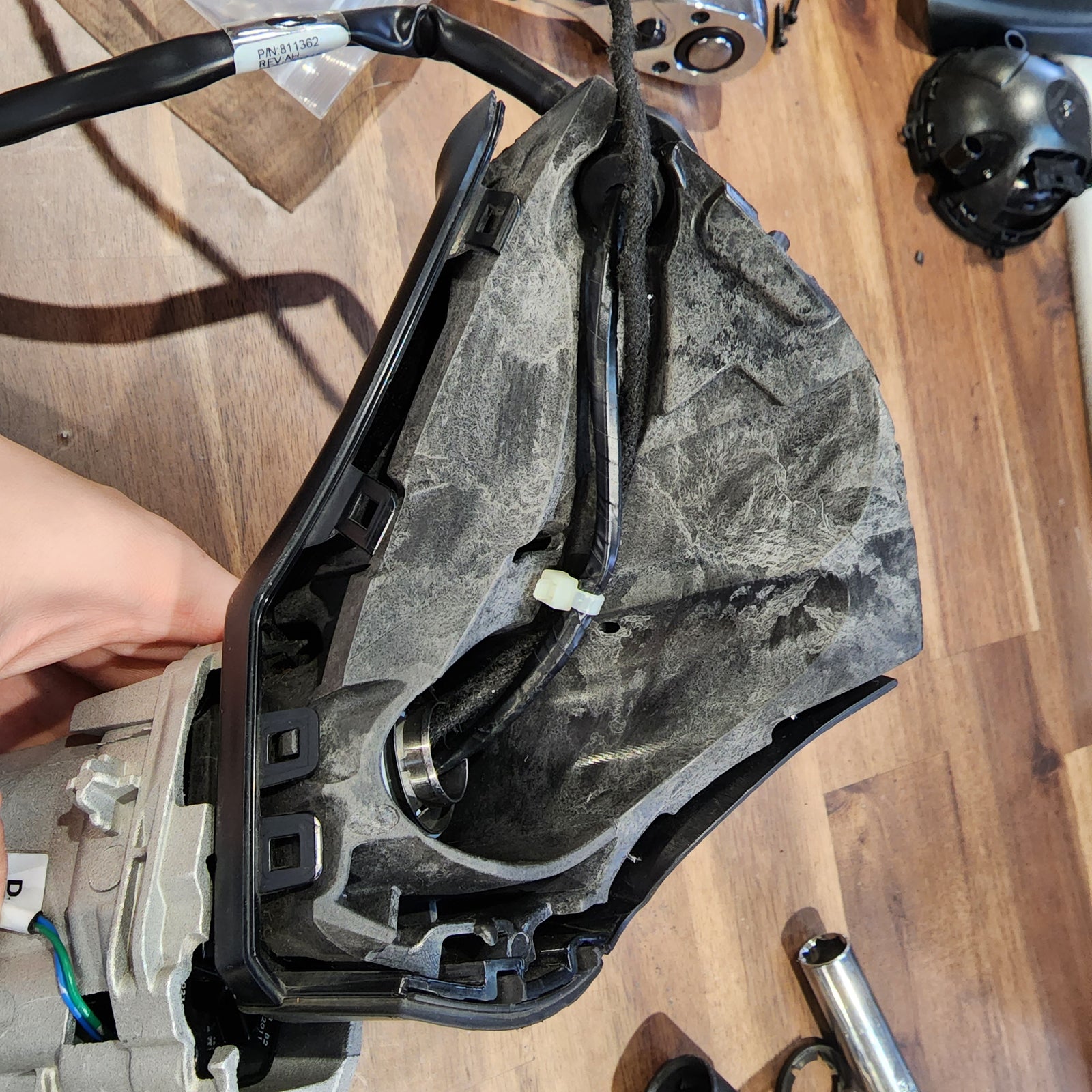
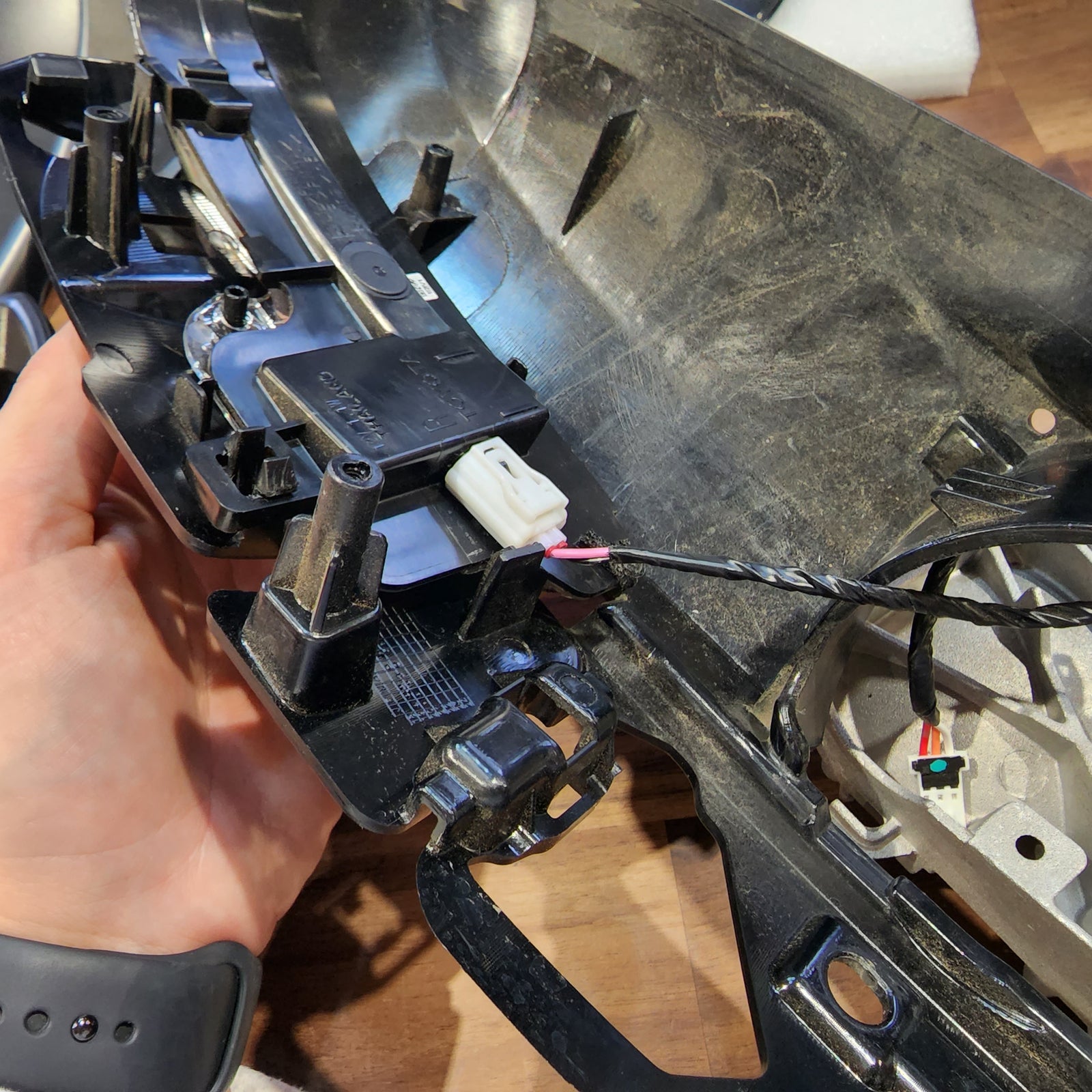
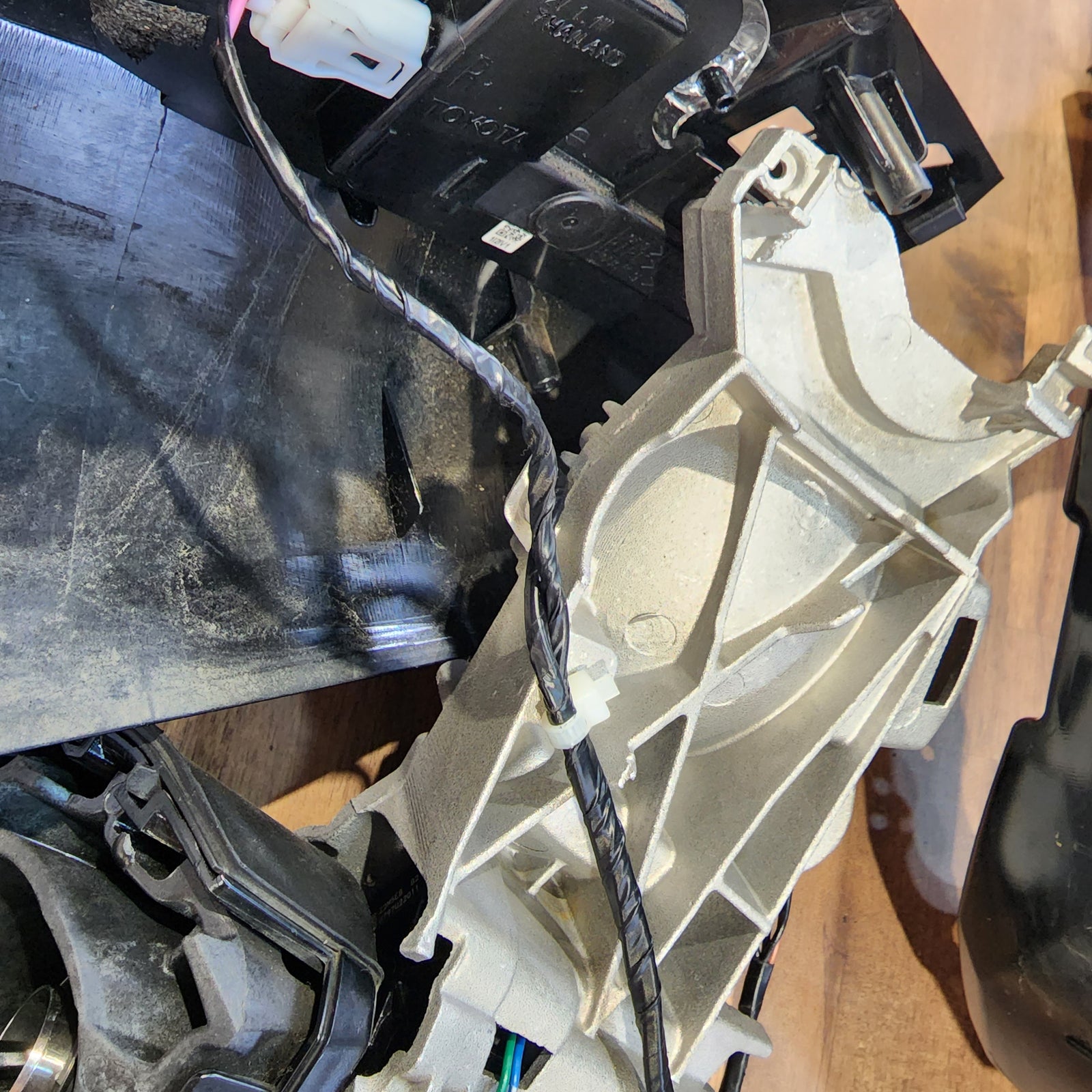
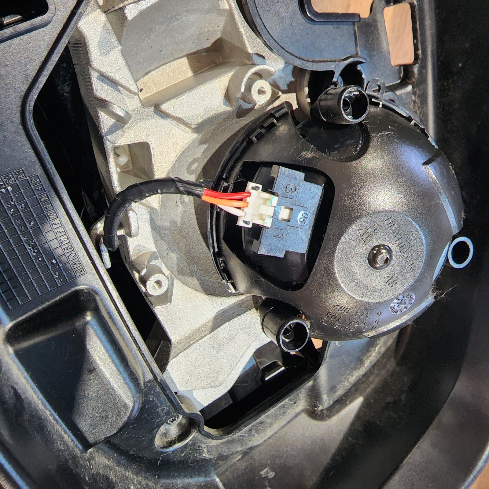
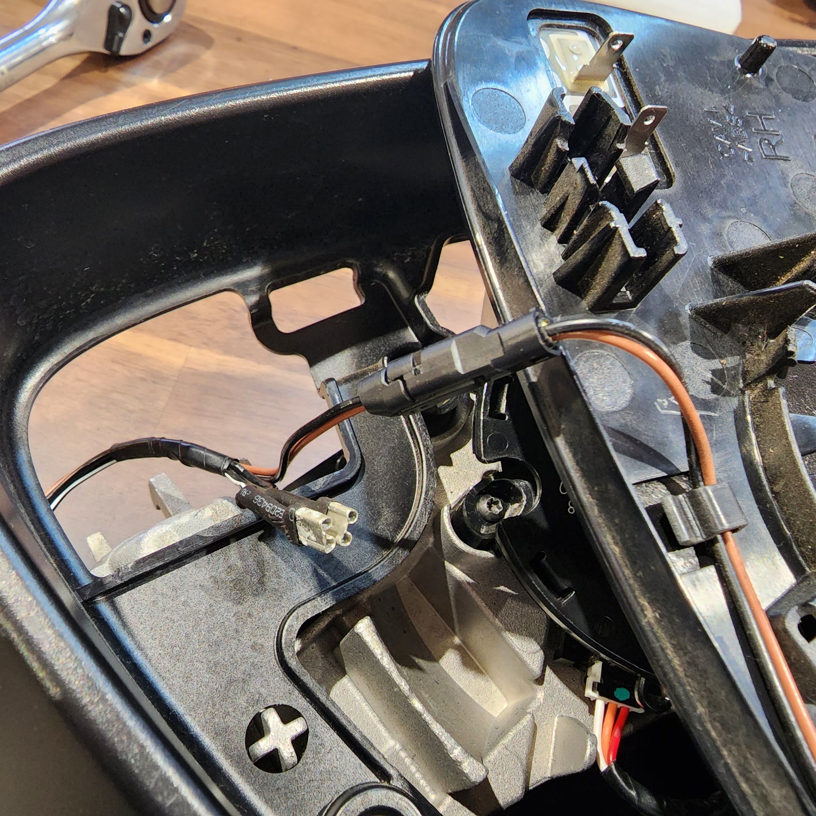
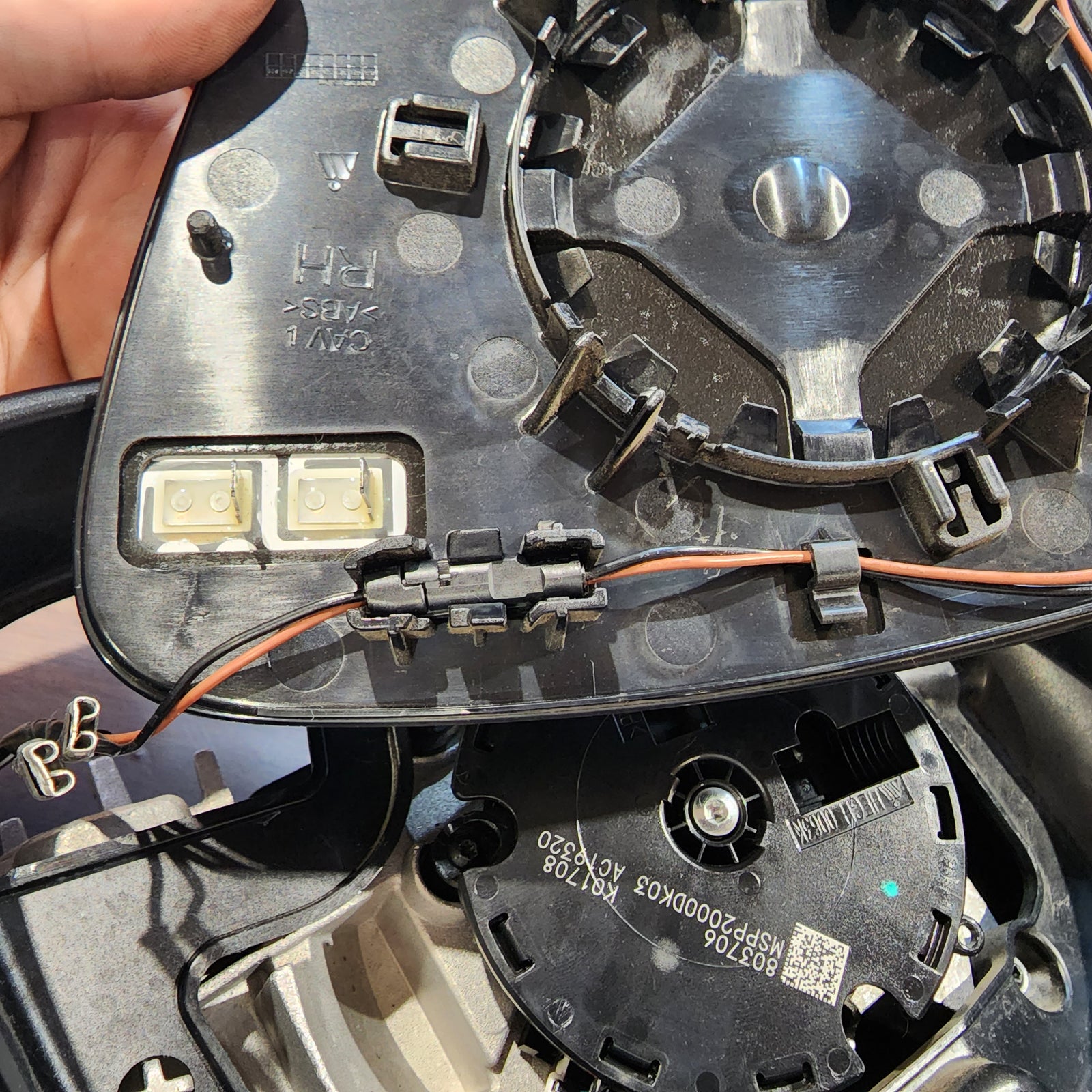
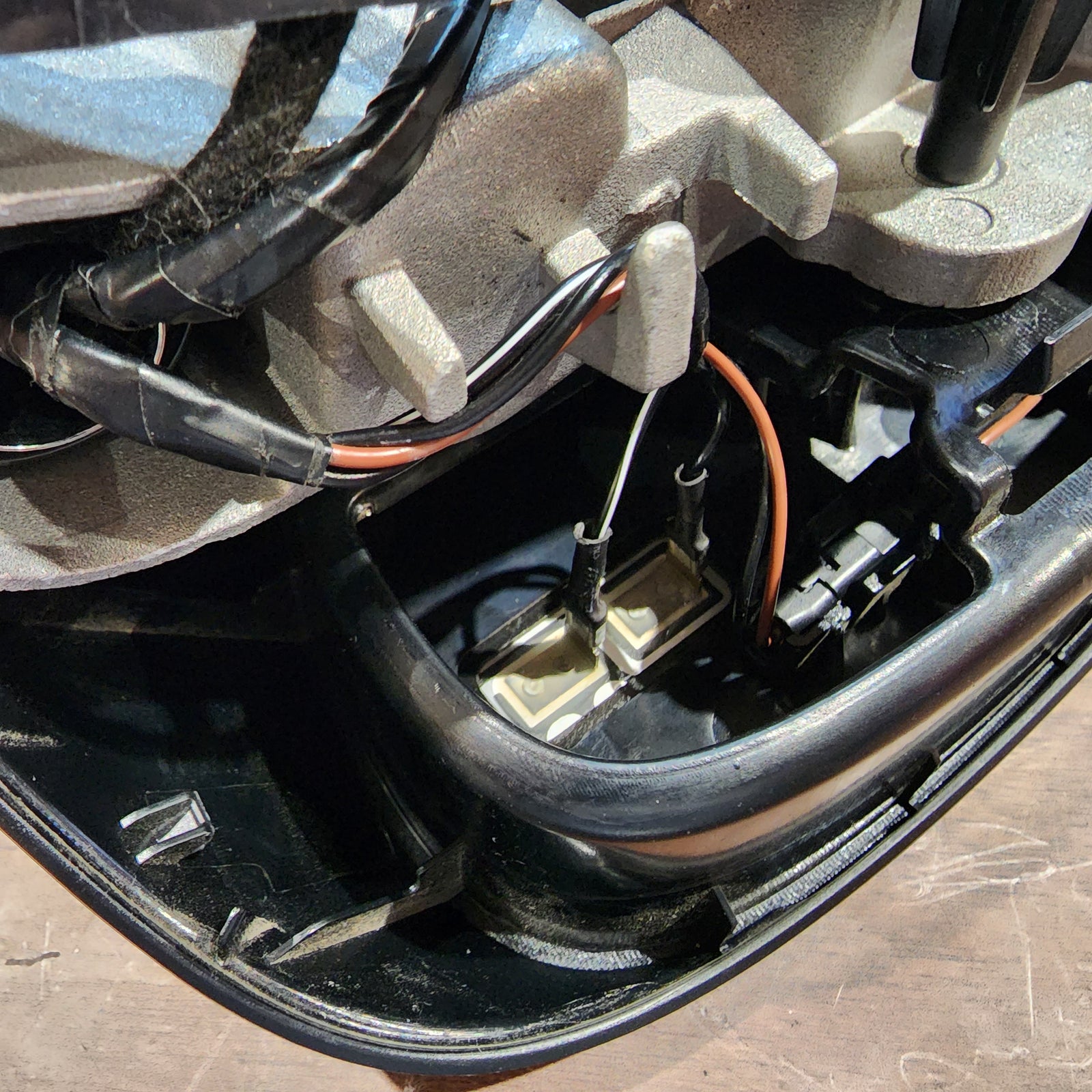
Now you can remove the rubber isolator to reveal the white connector and wires that are held in by a black grommet. Start with lifting the tab on the top of the white connector to release it from the metal clip. Directly following that, you may be able to just pull the grommet outward, but if not, use a small flathead screwdriver to get underneath and lift up. This now releases the wire harness.
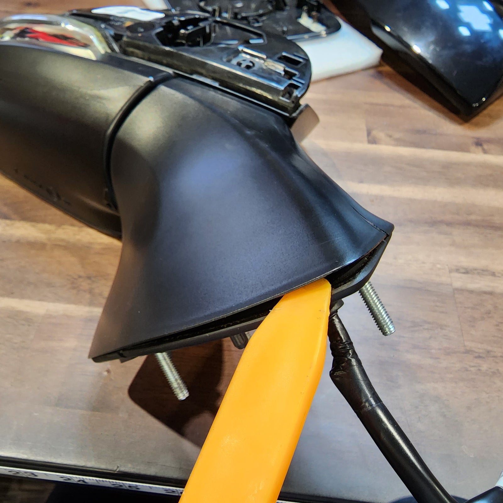
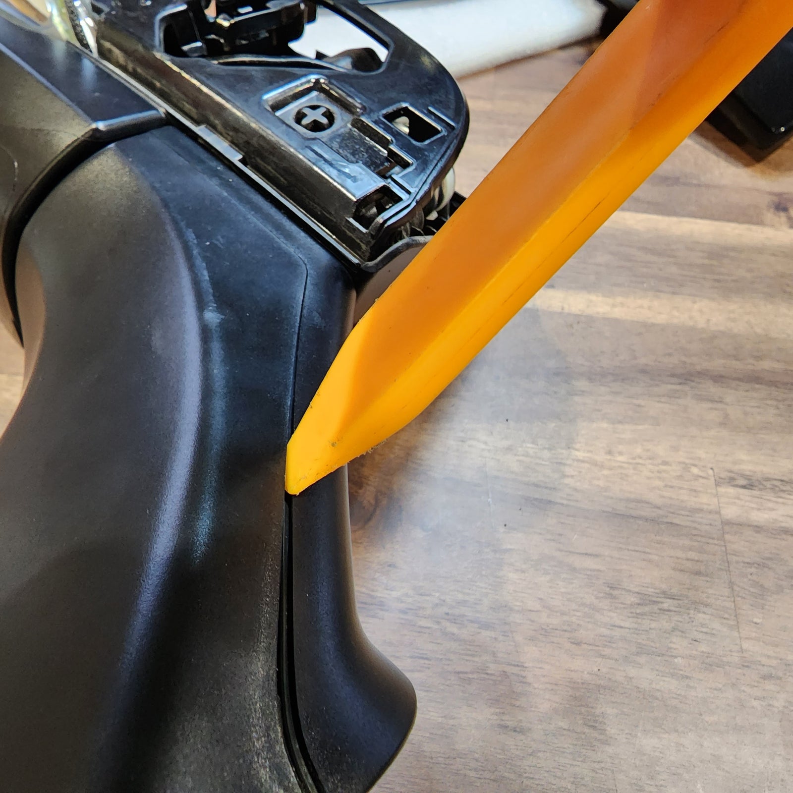
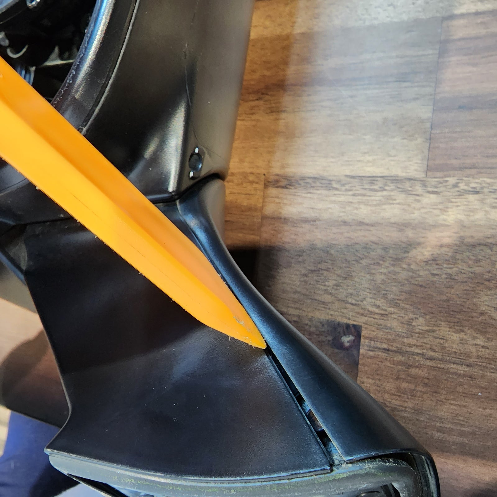
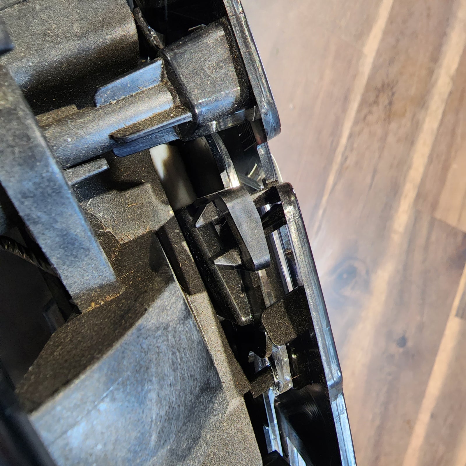
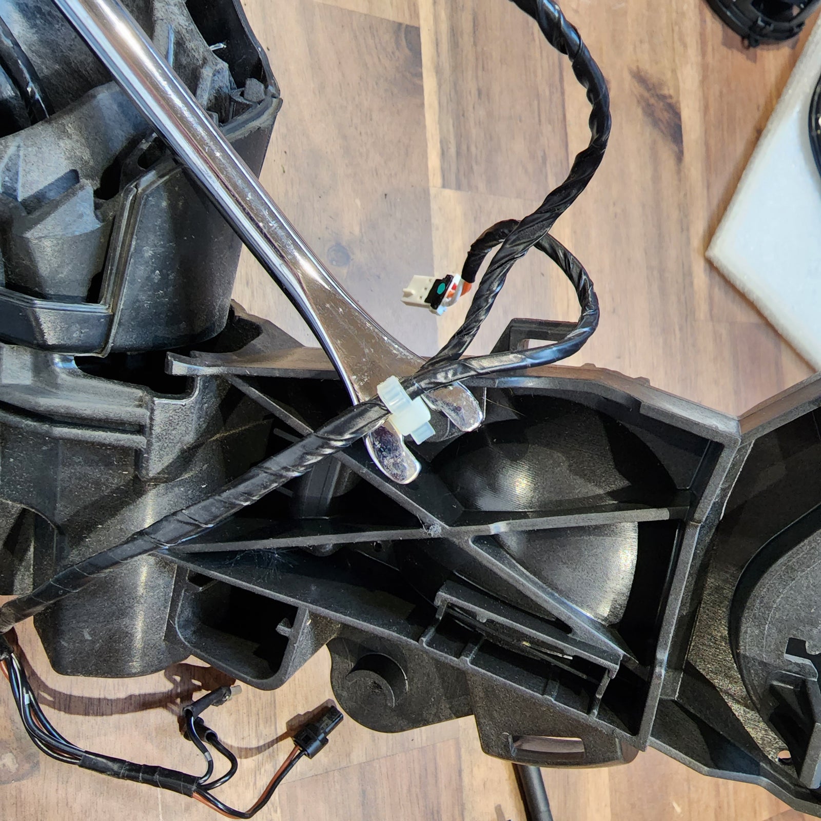
Using the trim removal tool, carefully pry open the lower mirror arm cover. It’s a handful of snap fits, so be careful not to break any. Once this is removed, you will be able to grab the wiring harness and slowly pull it through the hinge and all the way out of the mirror housing completely.
INSTALL IMAGES


STEP 7
-
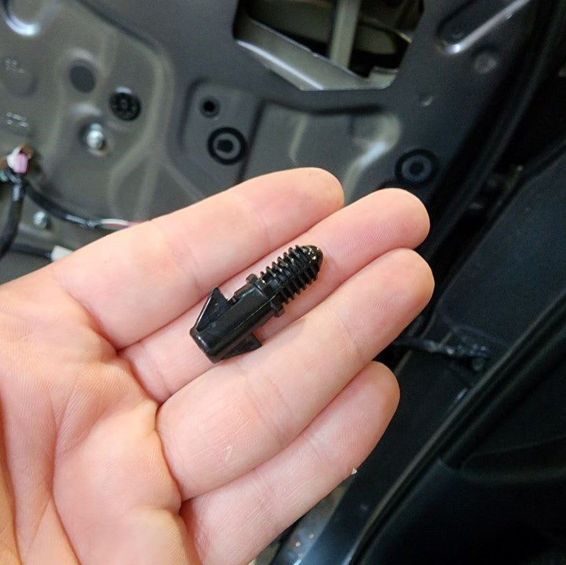
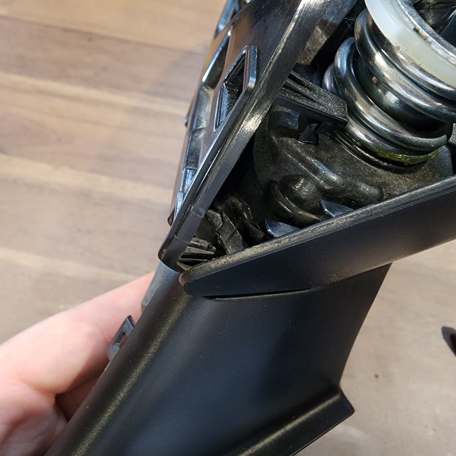
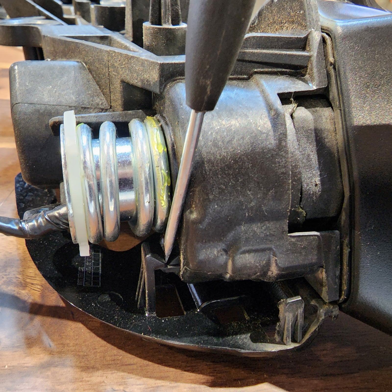
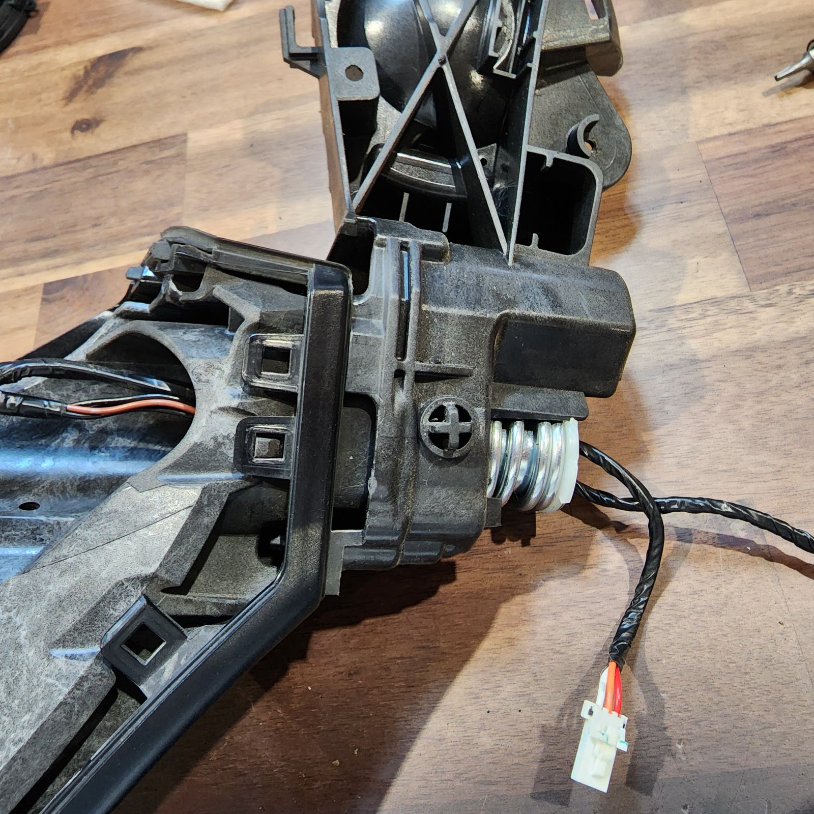
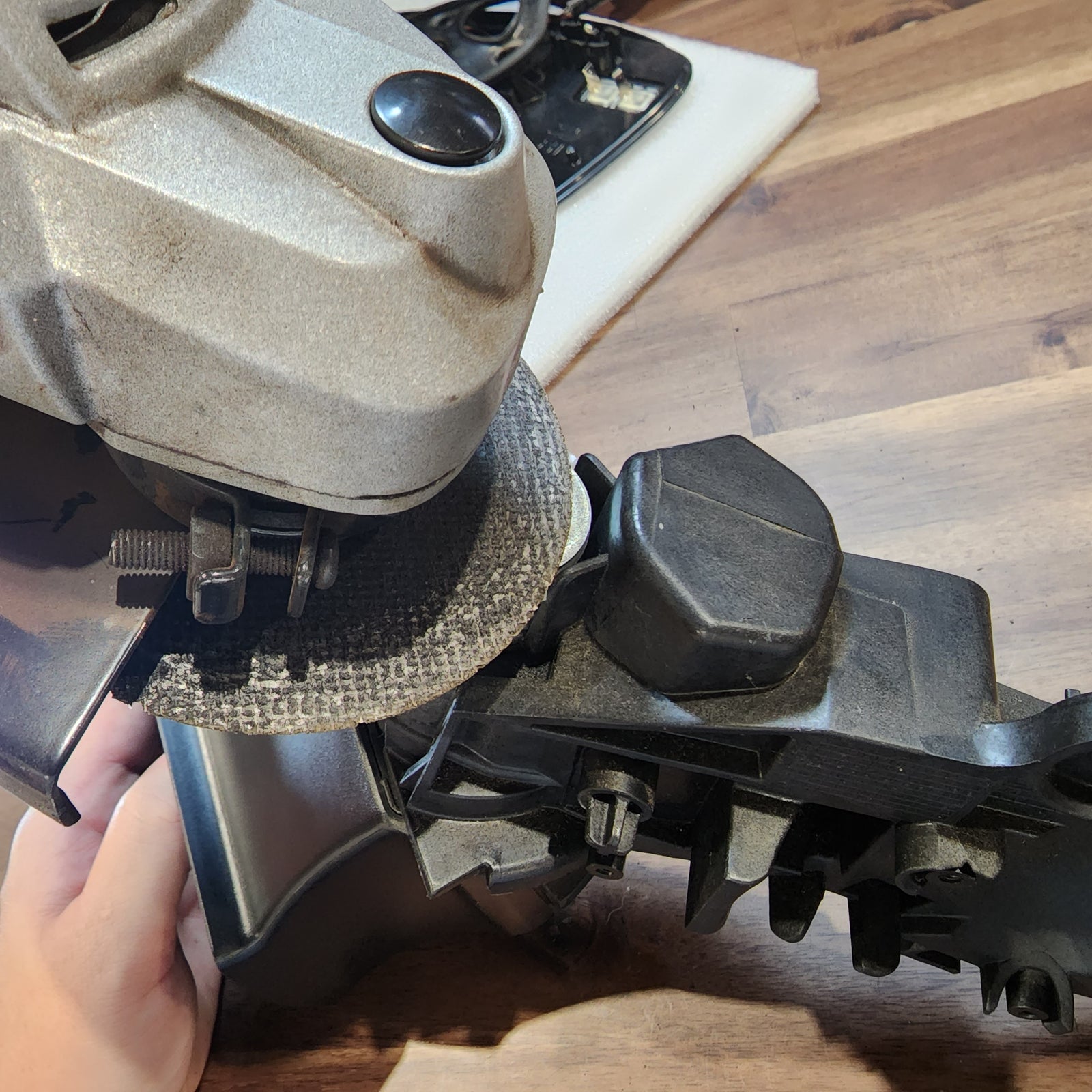
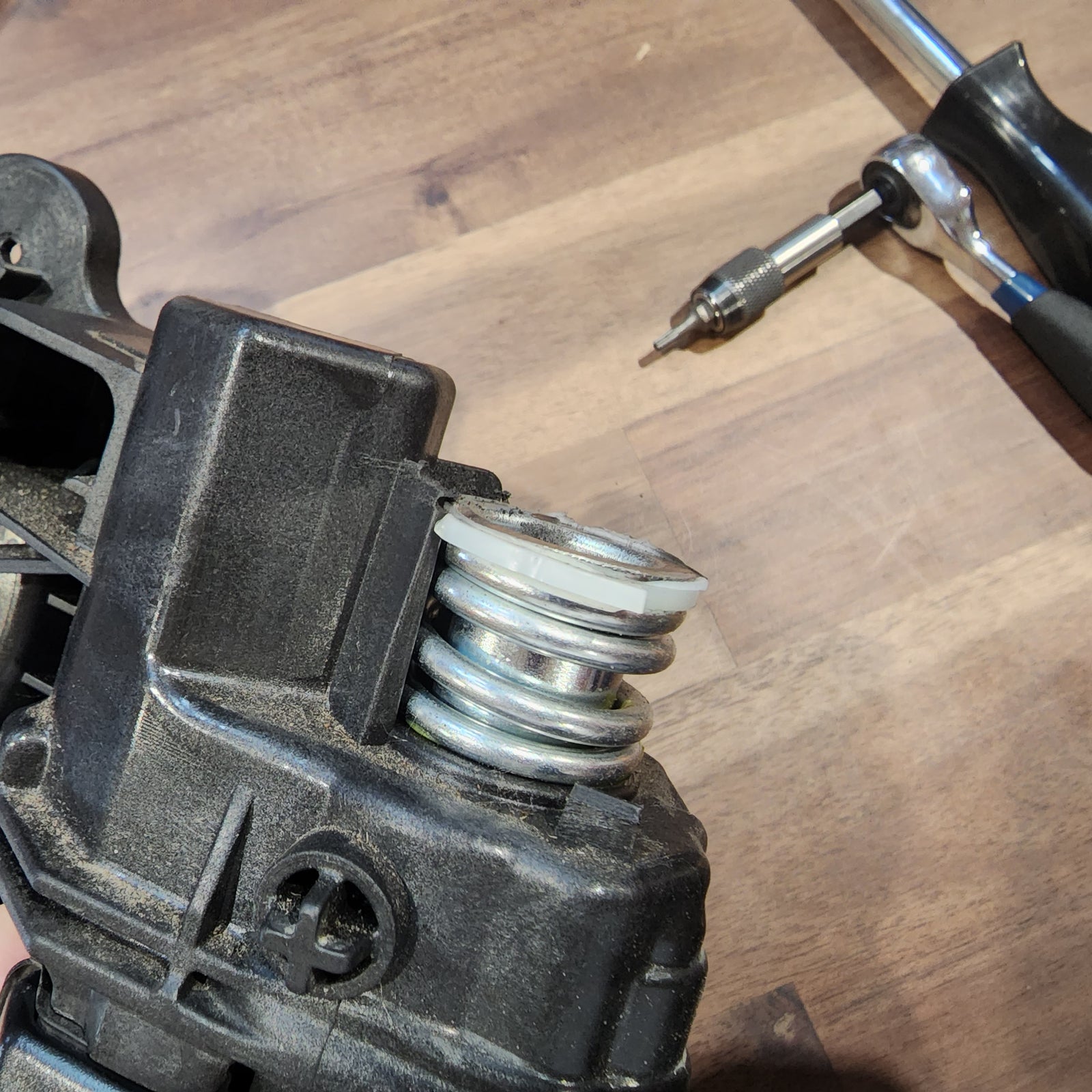
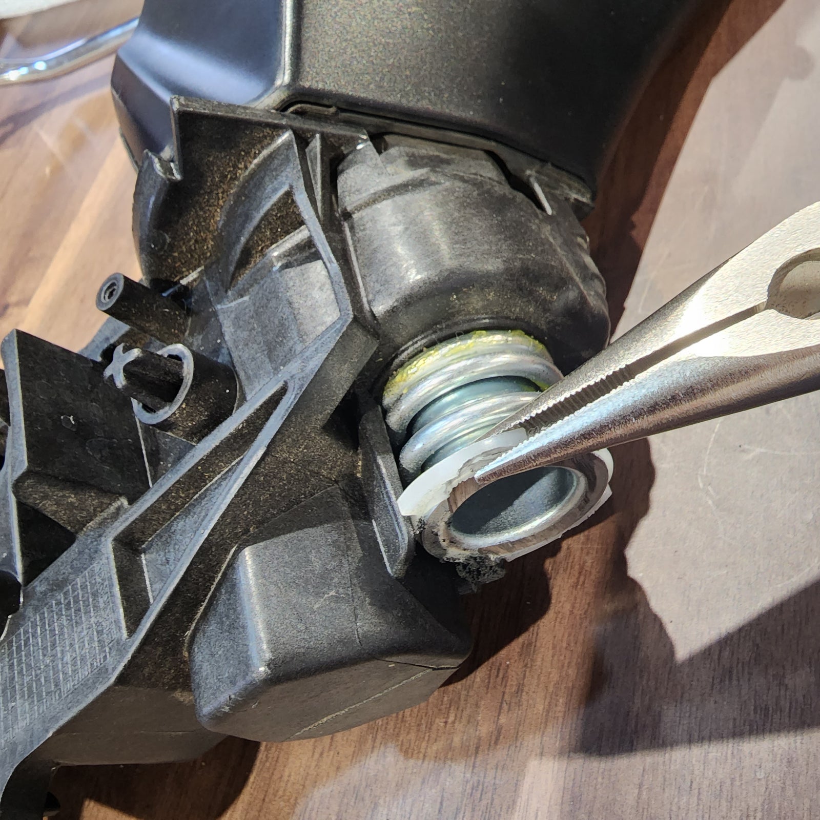
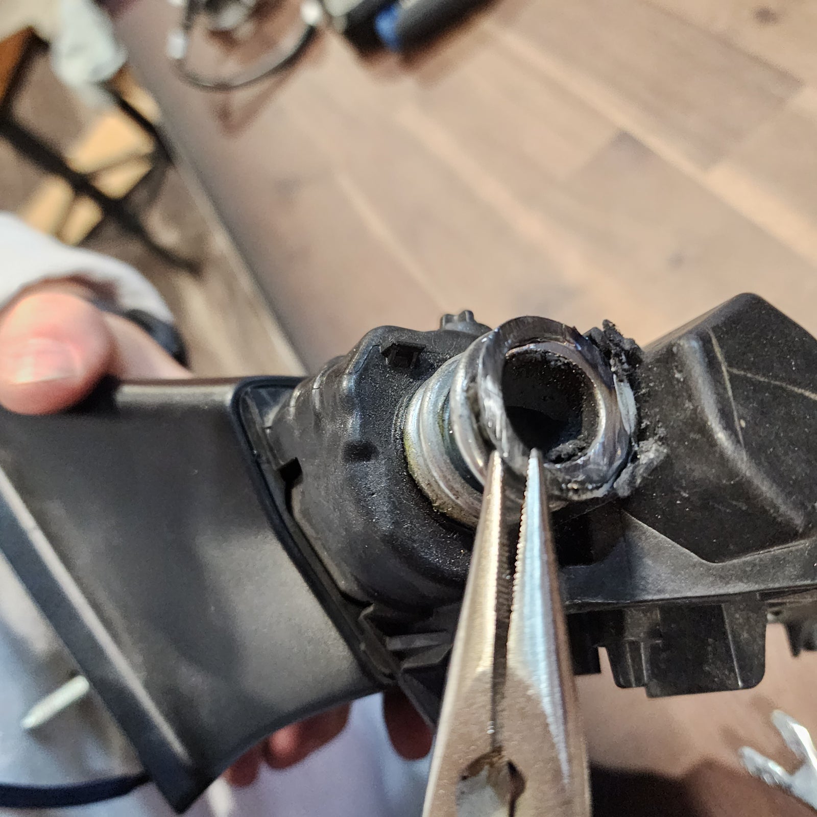
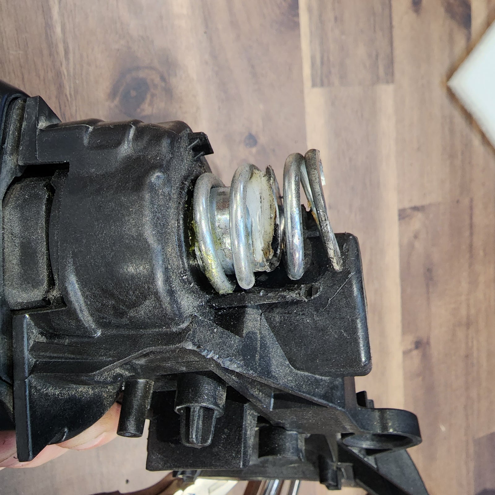
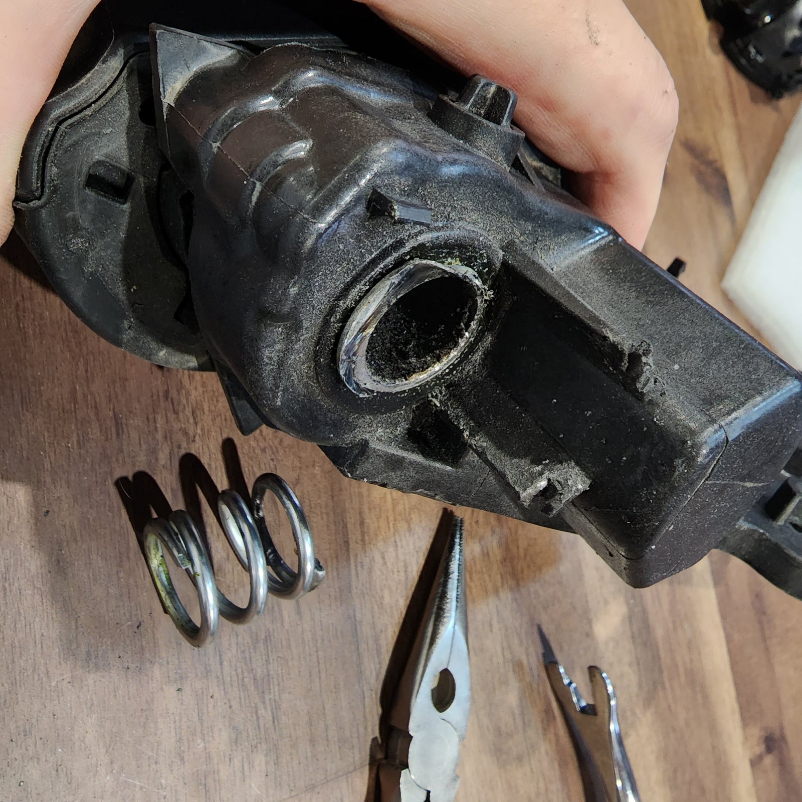
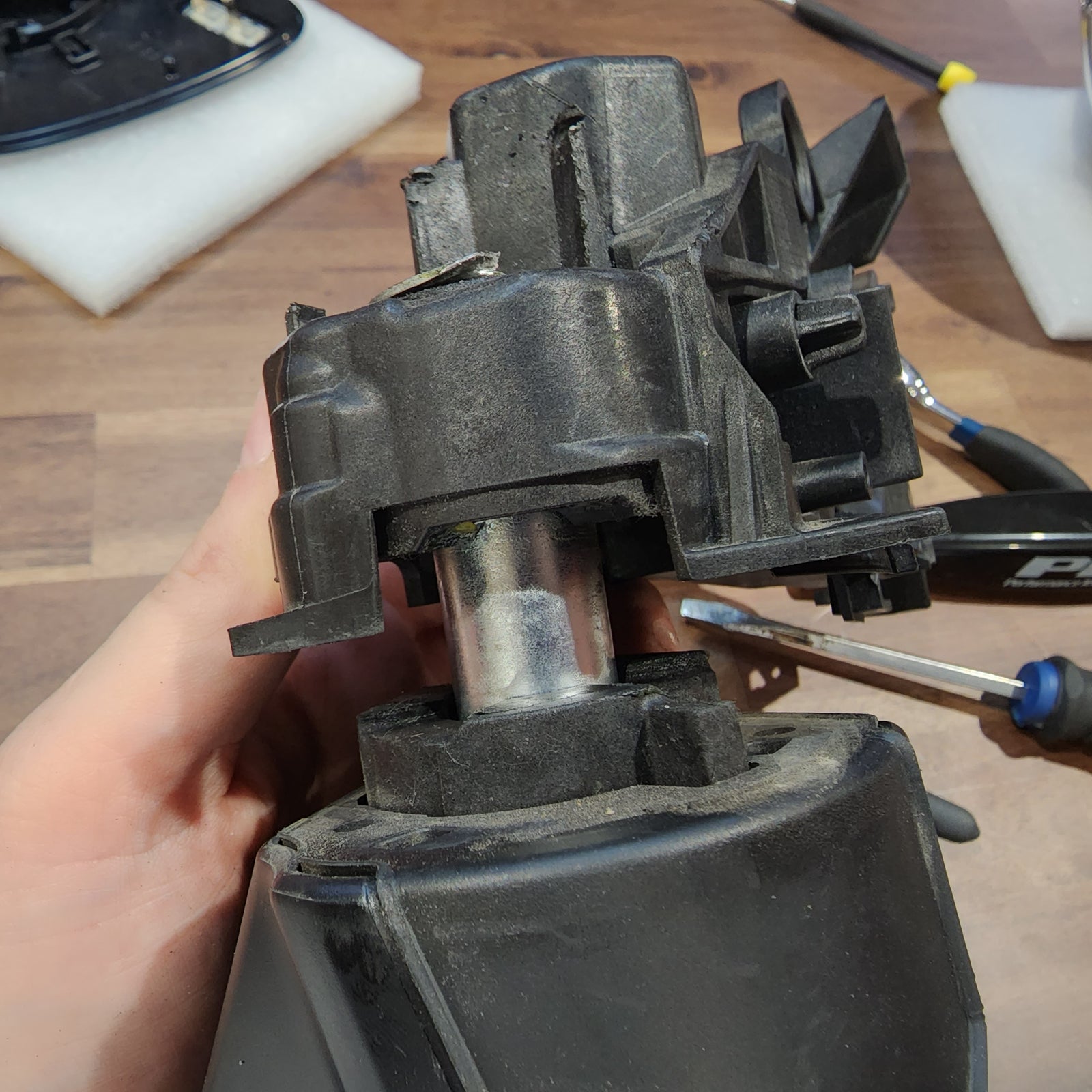
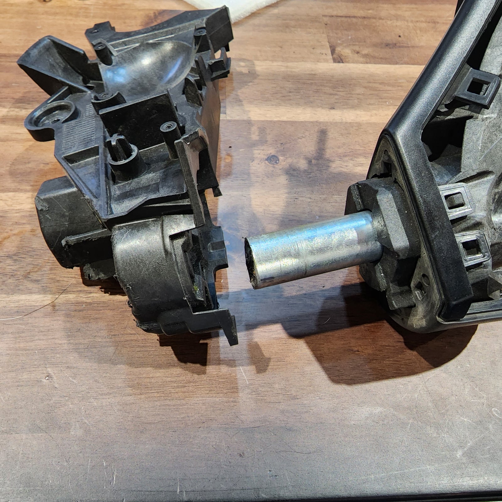
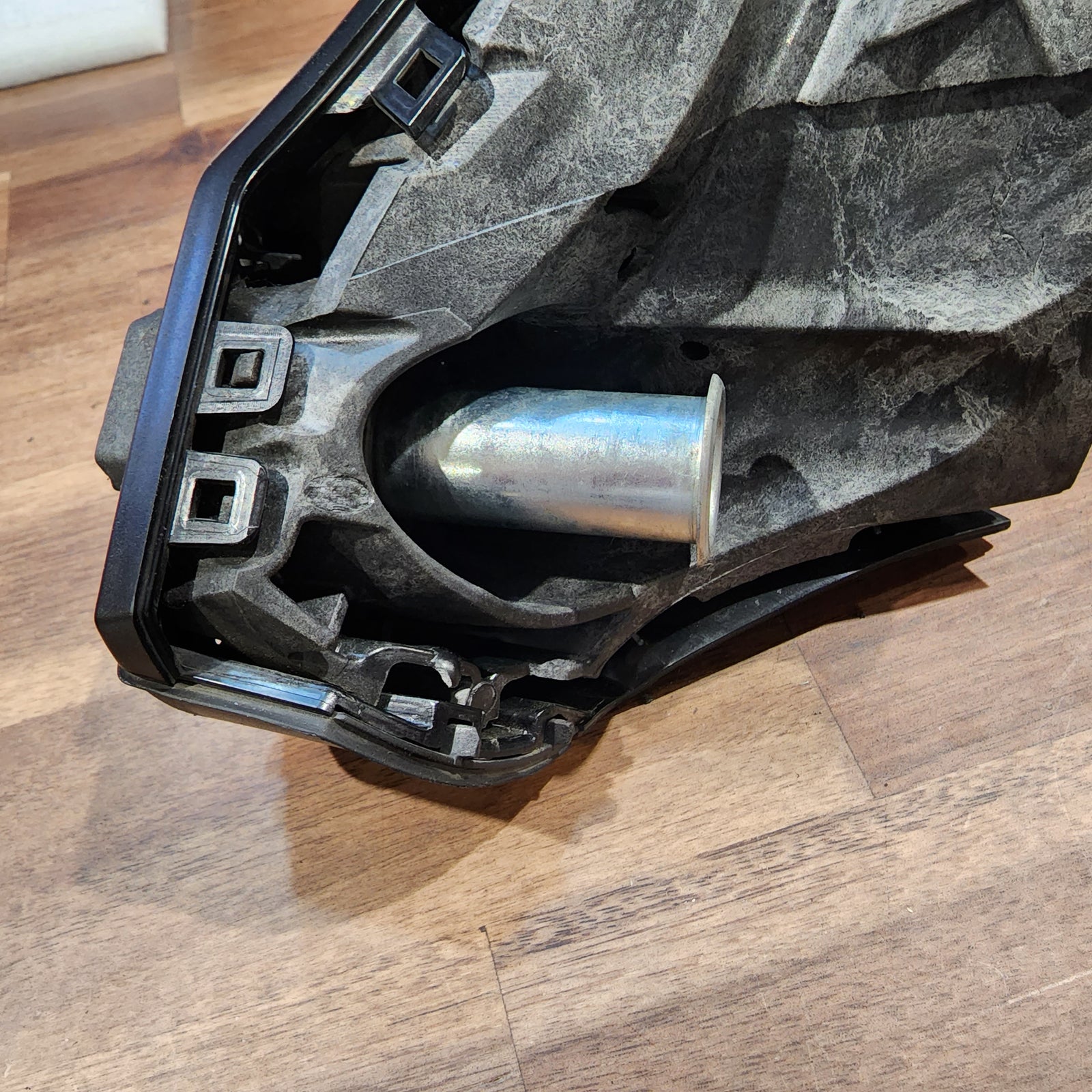
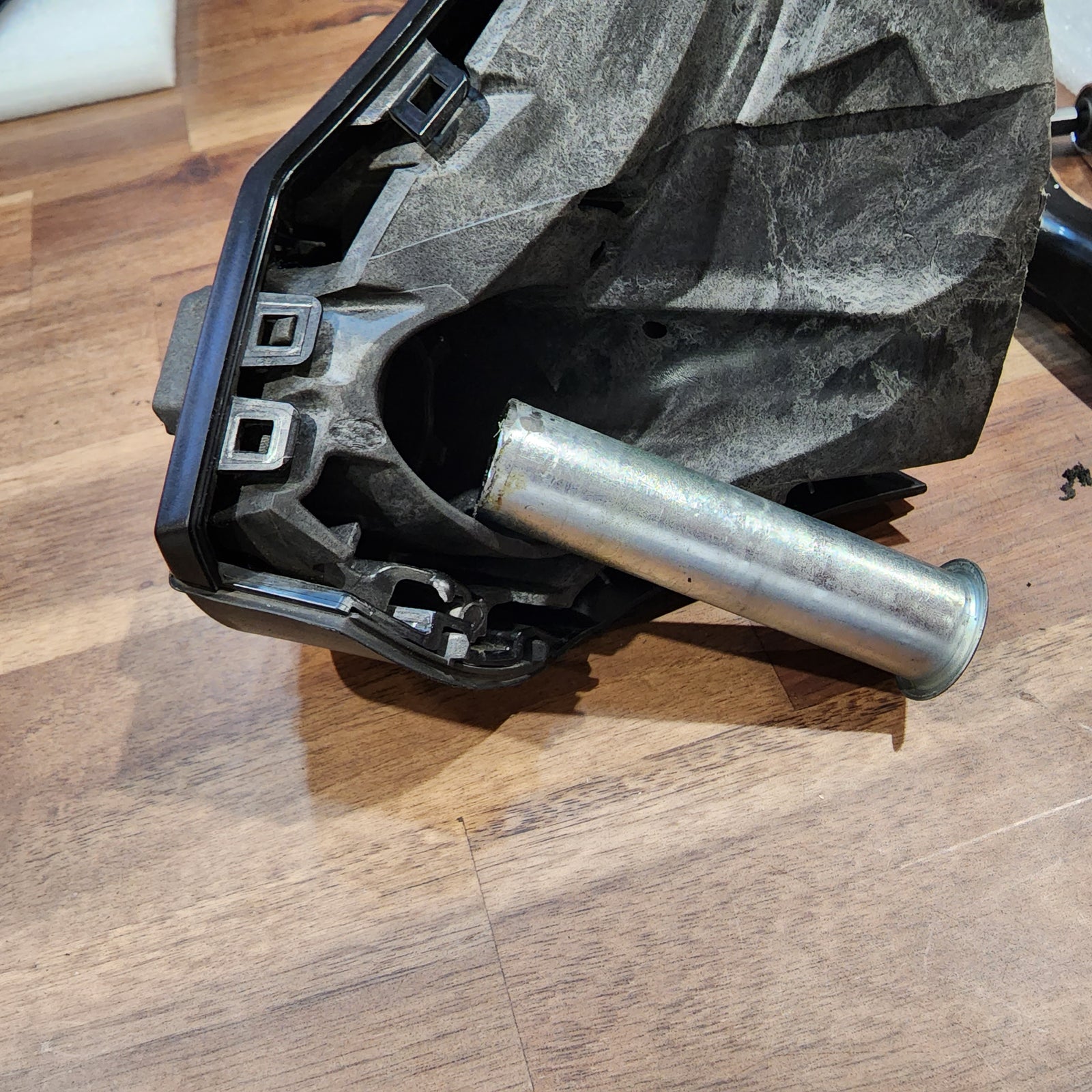
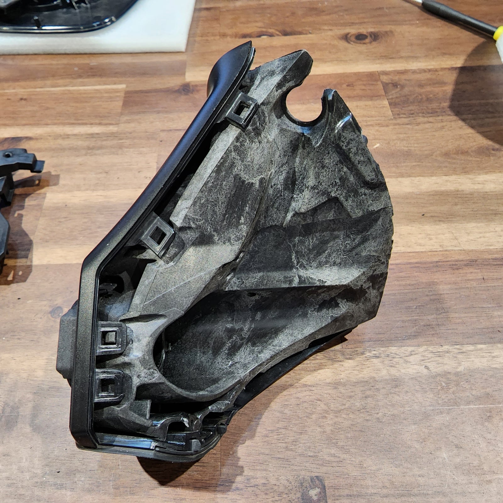
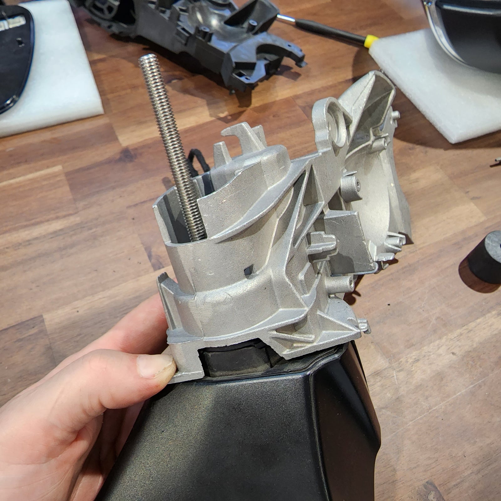
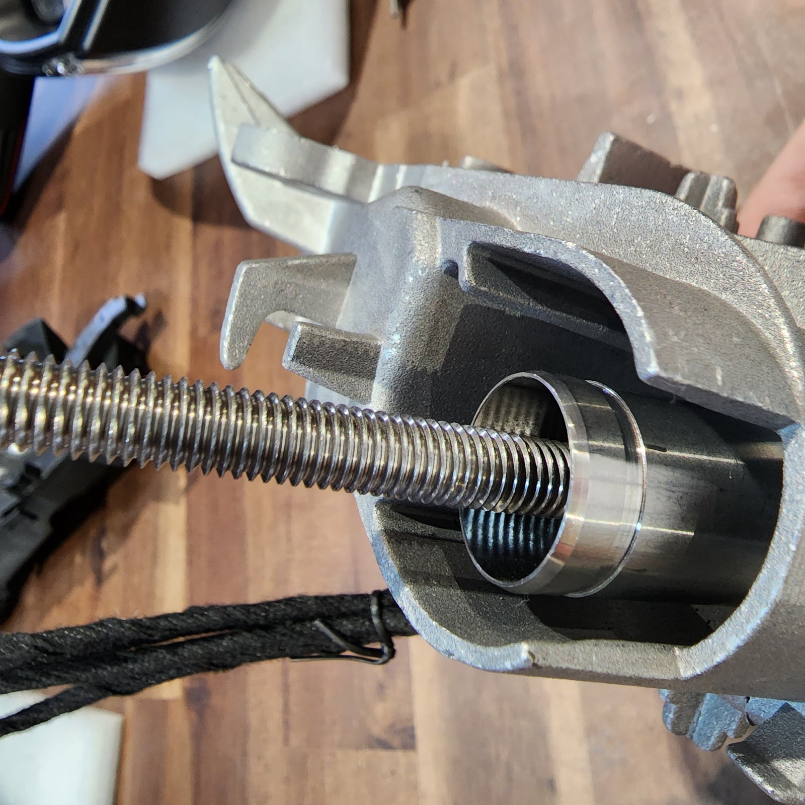
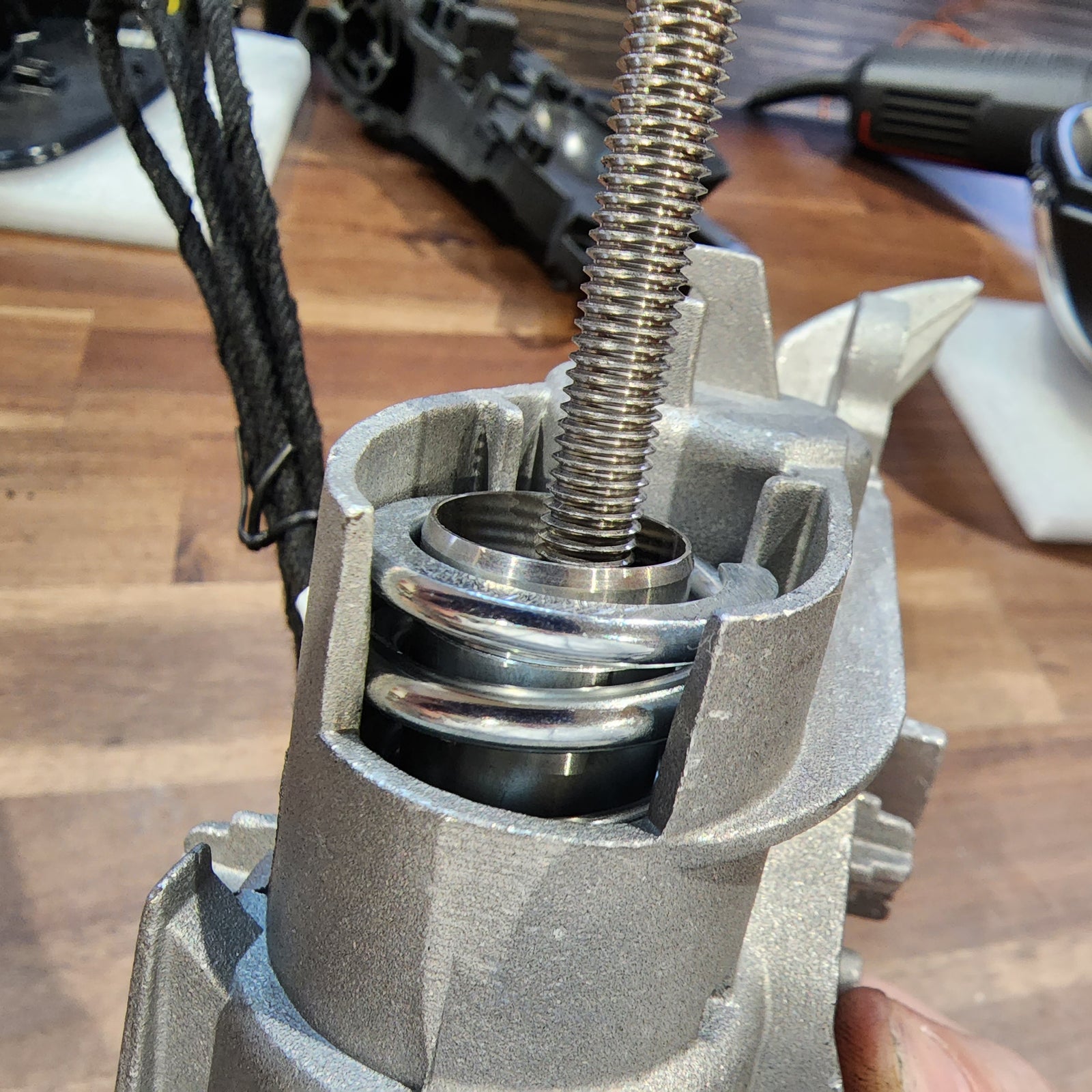
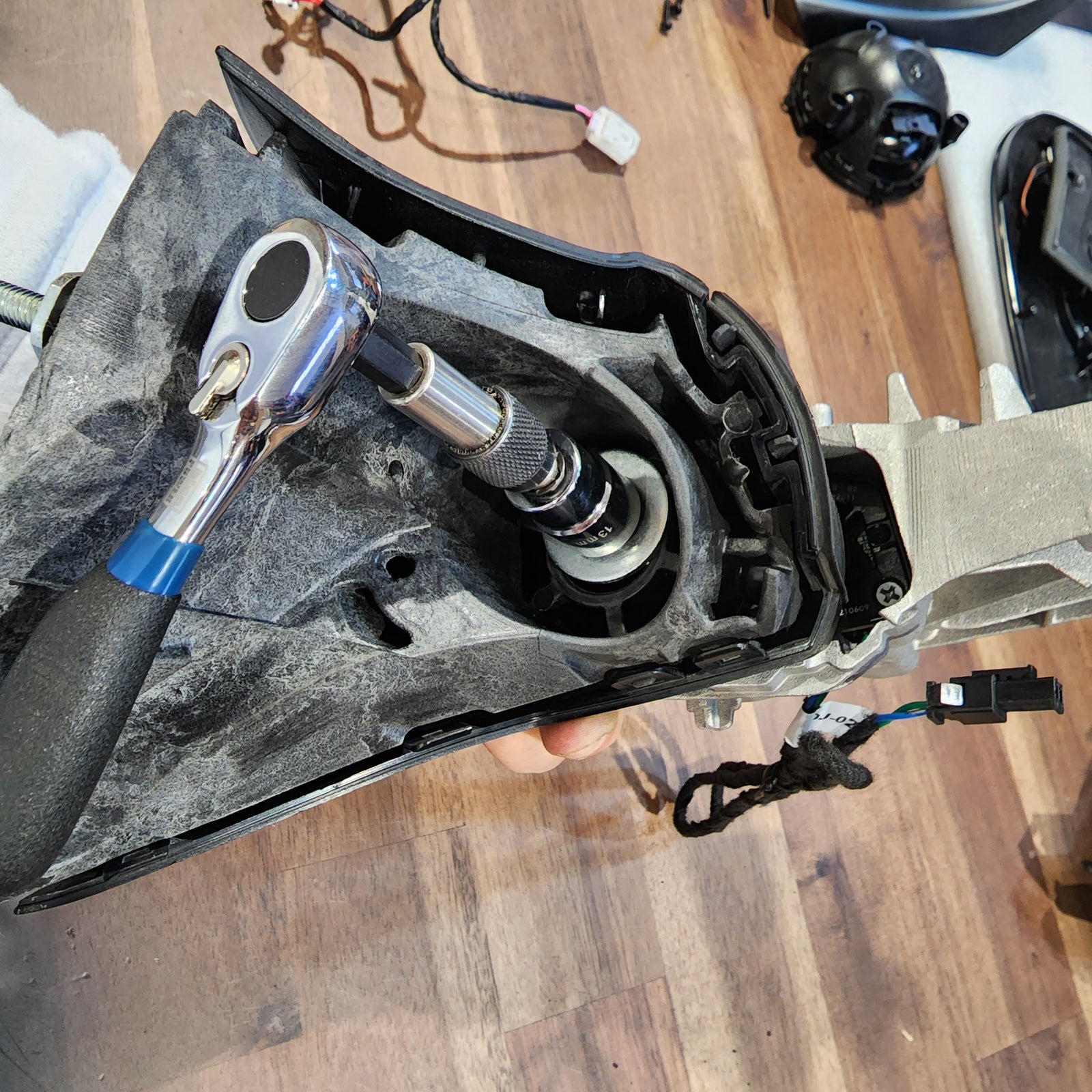
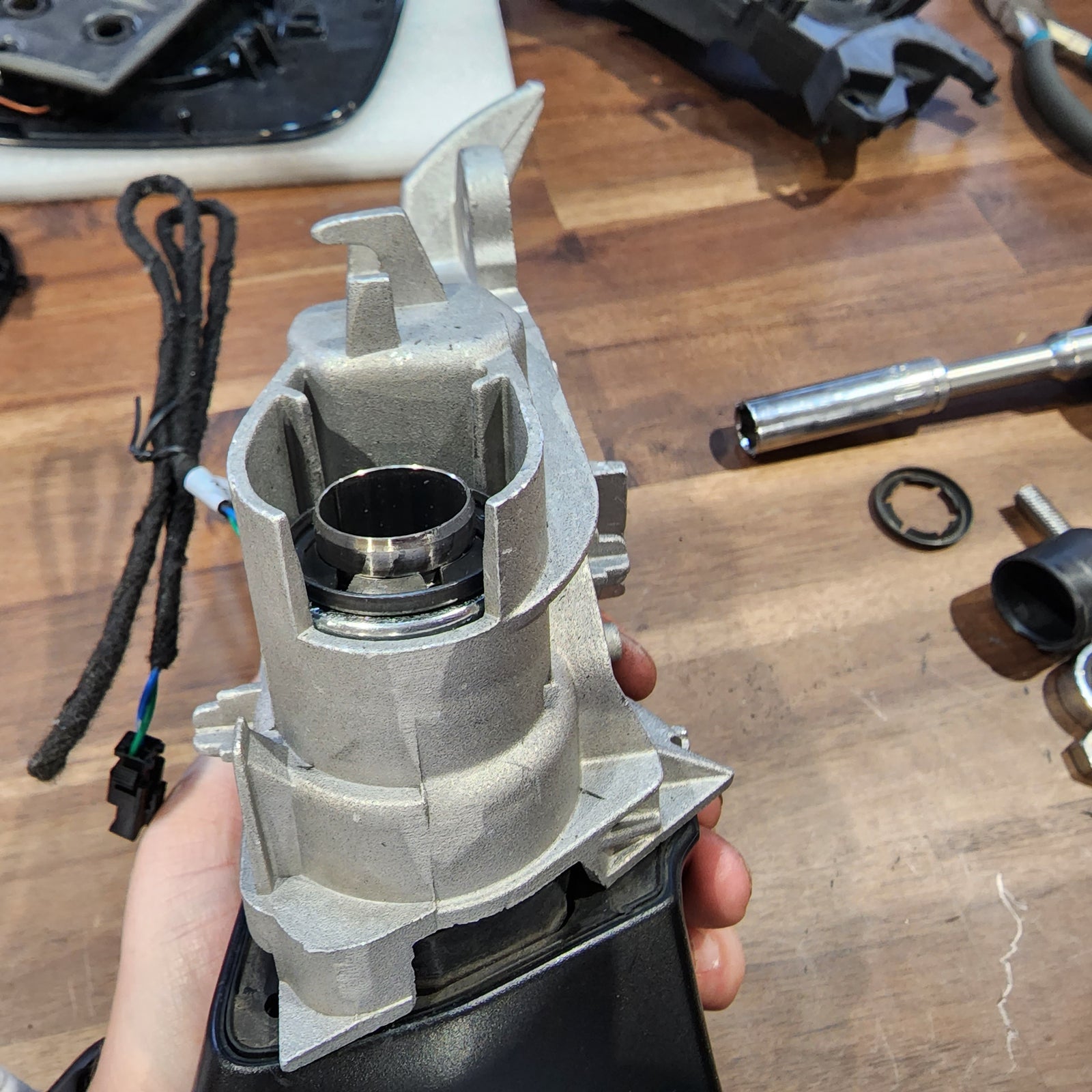
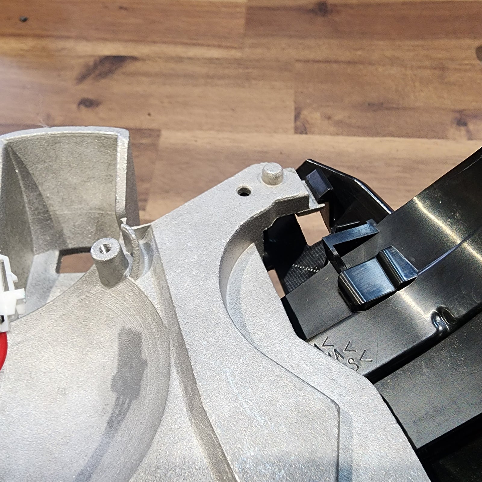
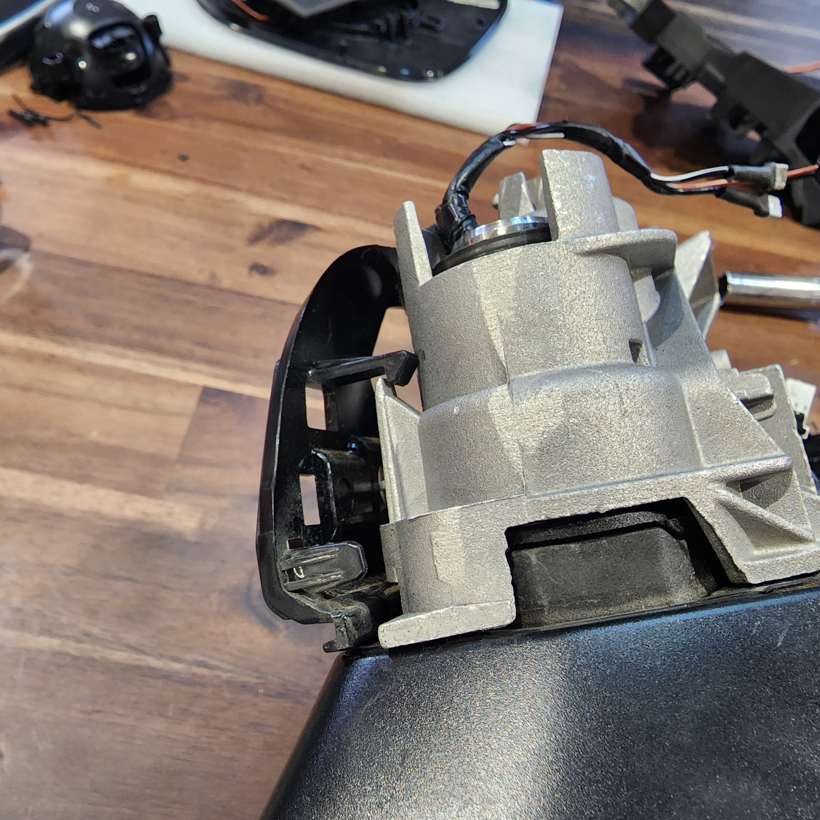
Bring out your dremel or your choice of tool for this next step. You will need something that can shave off the top of the metal iron pipe that is keeping the mirror spring-loaded in open and closed detents. BE CAREFUL with this step as the spring metal clip can go flying once it is released from the spring. It is recommended to wear eye protection.
The only part you will want to keep is the spring itself. You need to be careful not to damage the top of the spring. Once you have the spring released, remove all the little components. You have now 100% dissasembled your factory mirror at this point.
INSTALL IMAGES


STEP 8
-
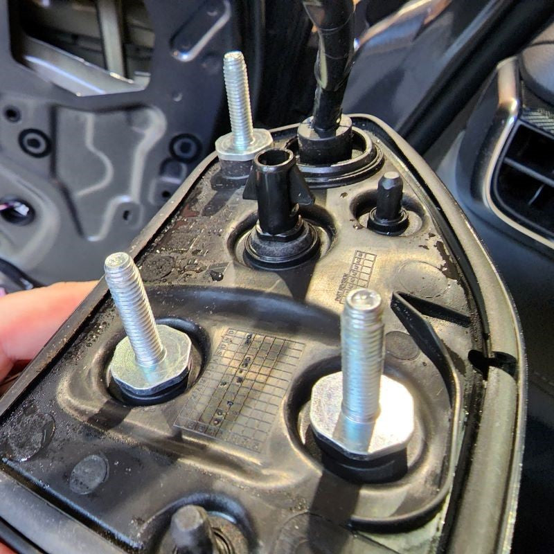
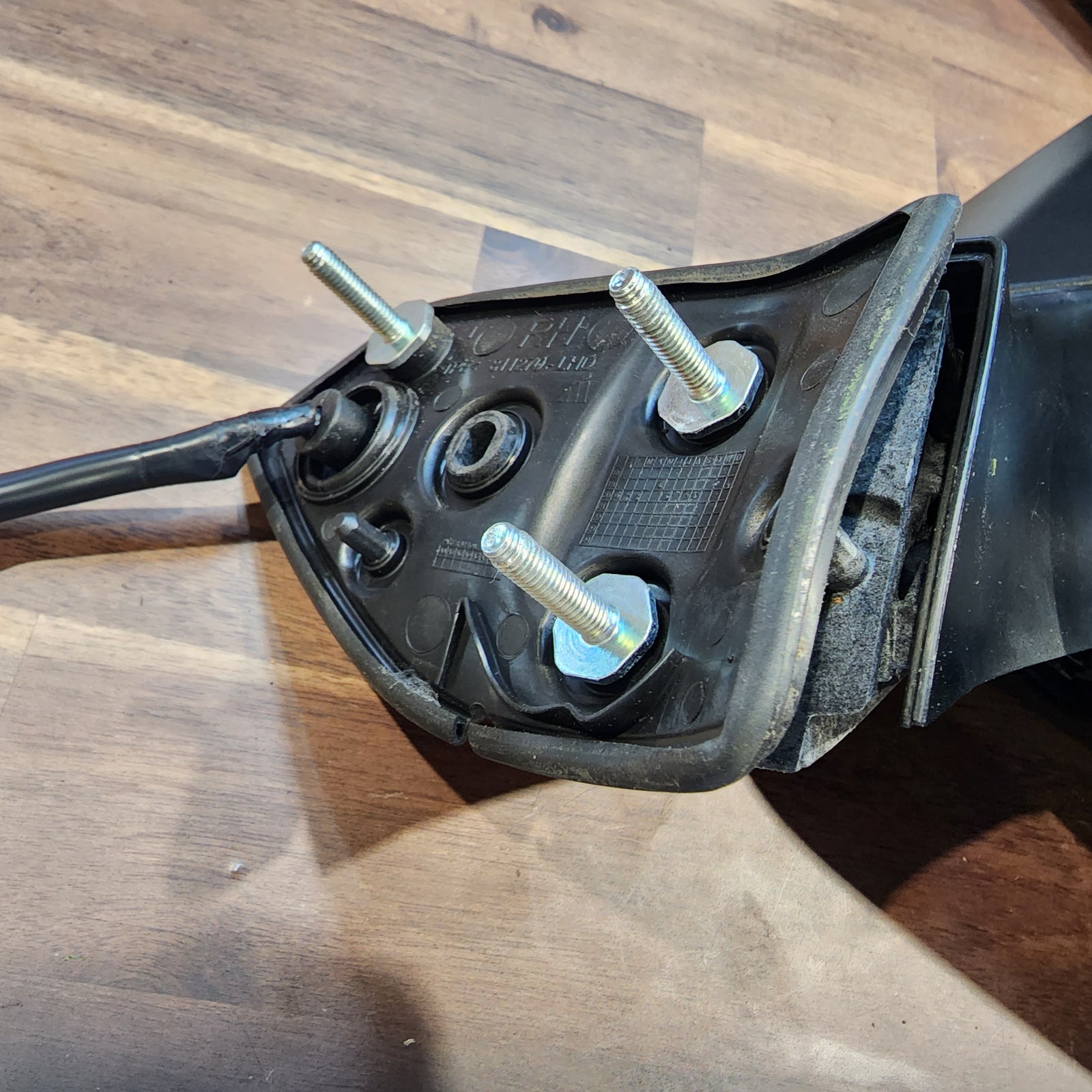
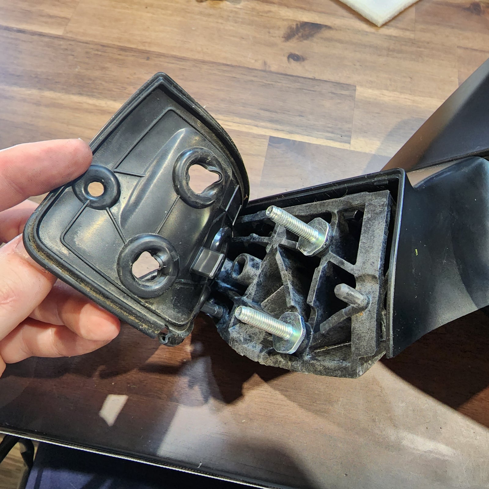
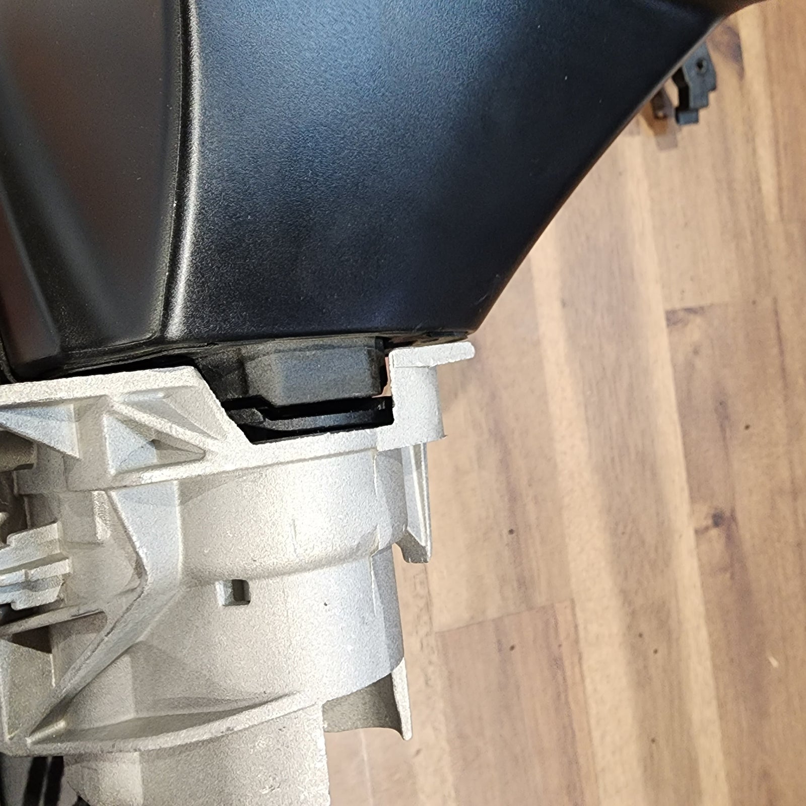
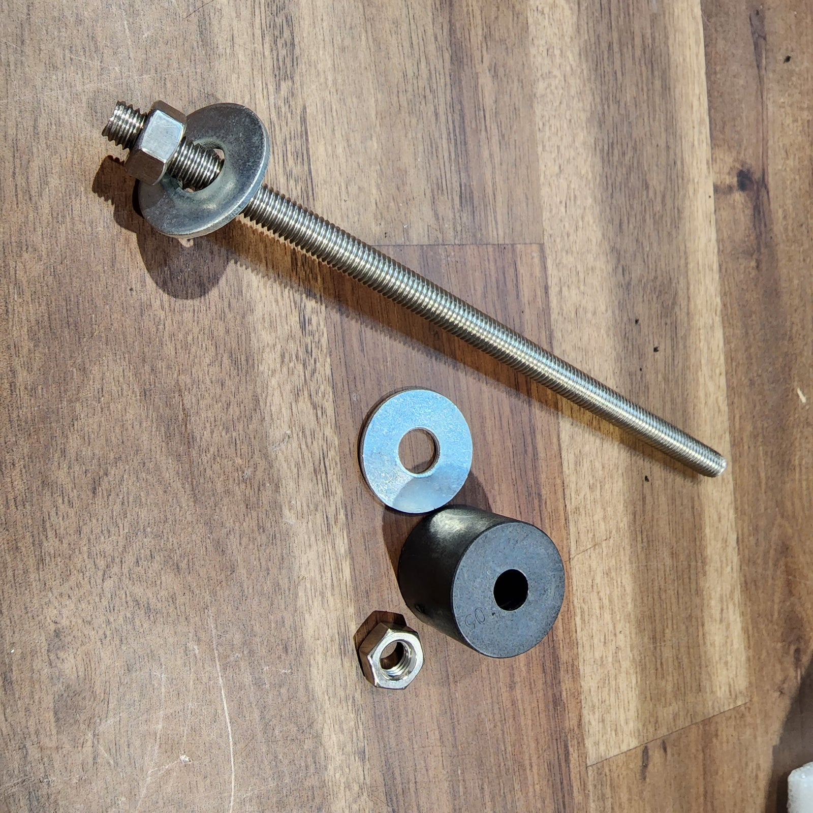
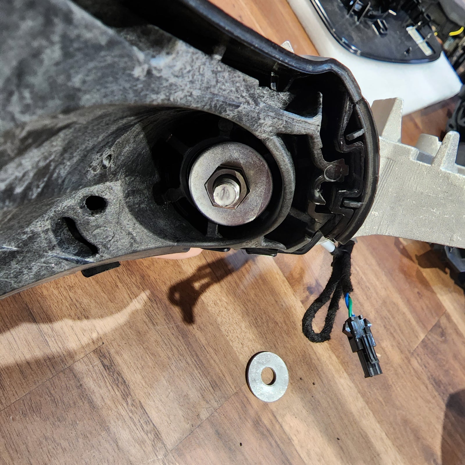
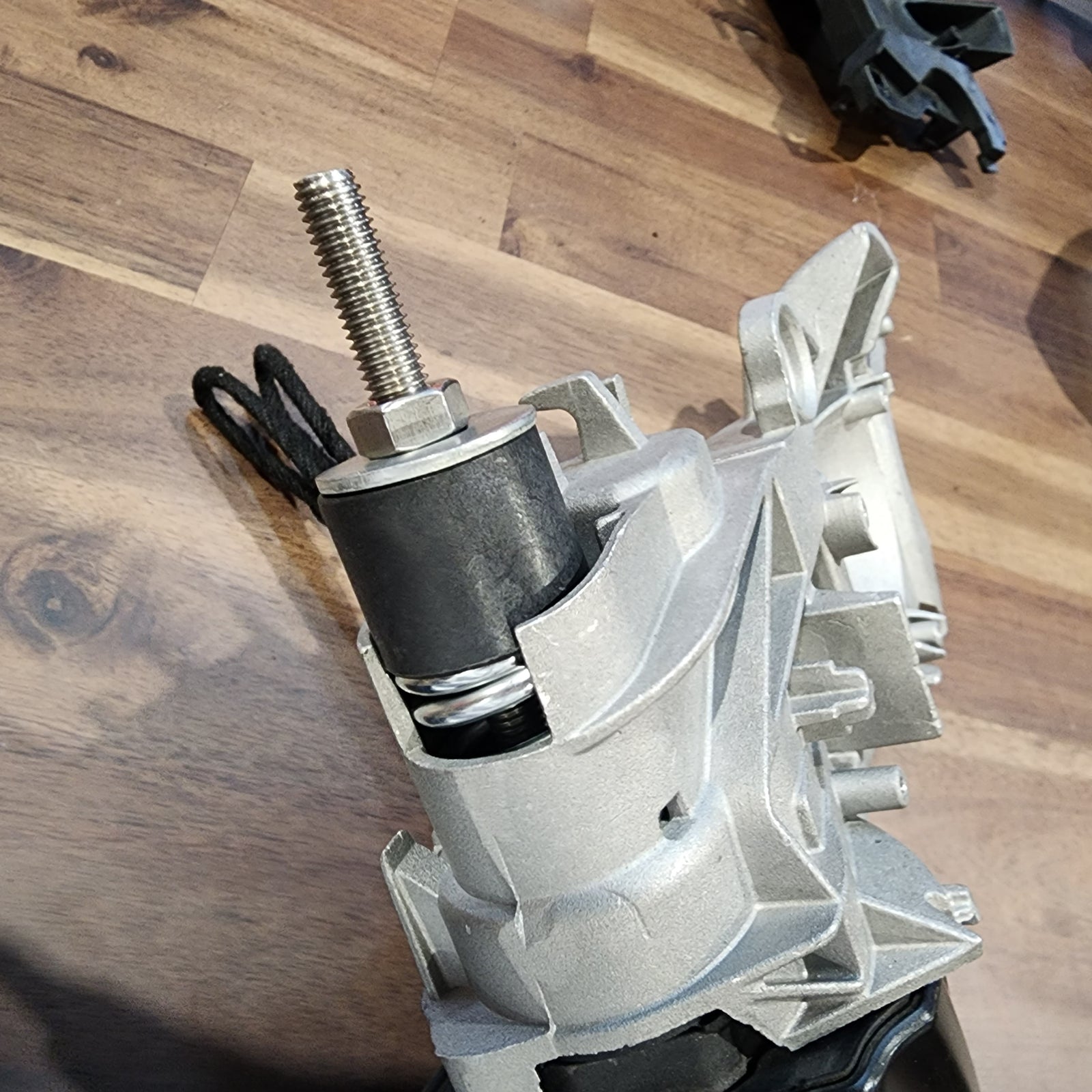
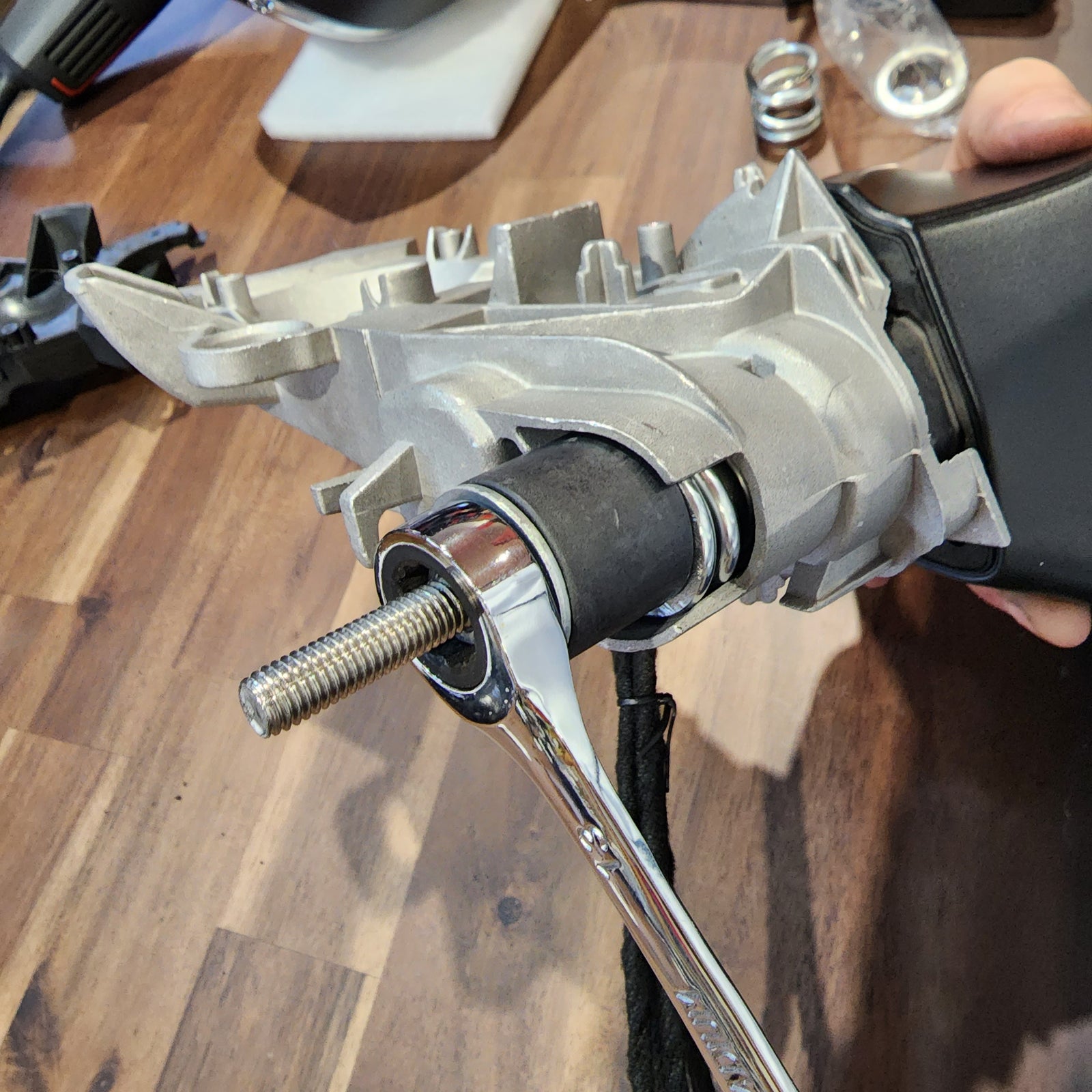
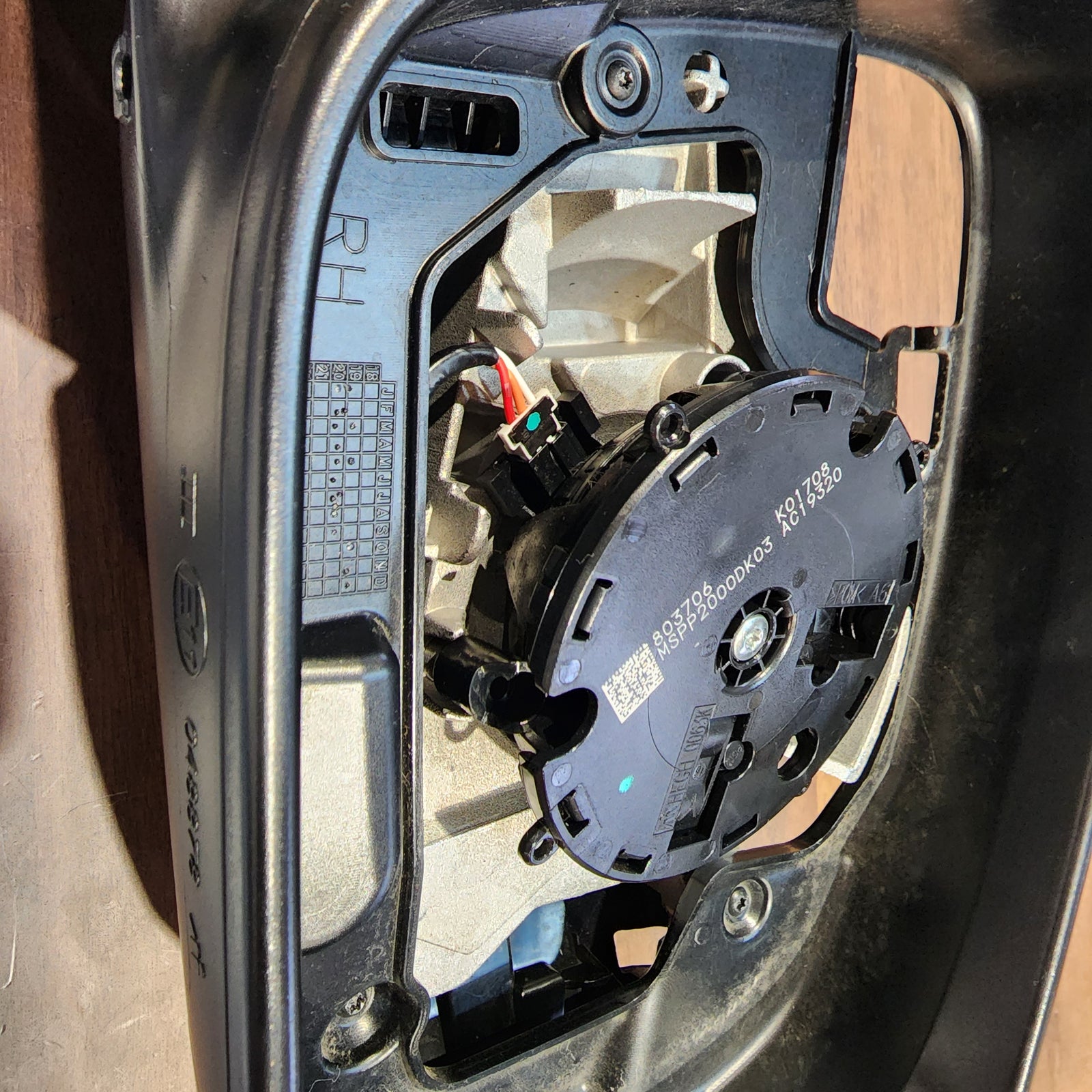
Remove the old connection arm plate and replace it with the new connection arm plate with motor. Here you will also use the new hardware to compress the spring back into place.
Lastly, compressing the spring back into place can be tricky but be patient. You can use a racheting wrench or deep socket to compres the springdown. Once you have all the new hardware secure, your new connection plate arm will be held in place.
INSTALL IMAGES


STEP 9
-
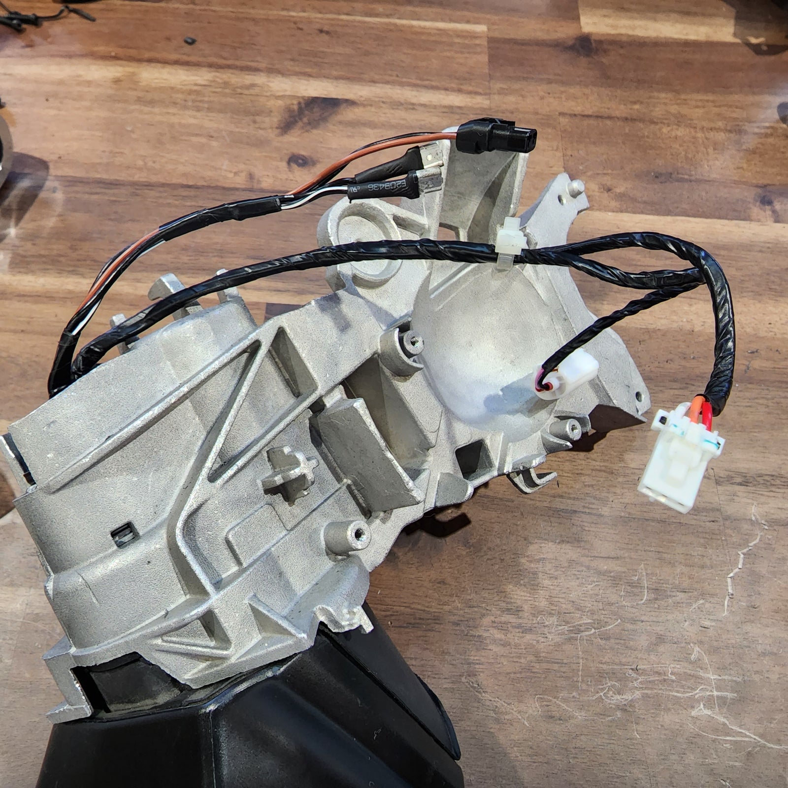
Tidy the wires up (including the two new wires from the motor) and route them back through the hole in the new arm bracket.
All screws can be added at this time – just follow the steps you took previously, except backward and use the photos below for reference.
INSTALL IMAGES


STEP 10
-
Now, if you didn't do both mirrors at the same time, grab the other mirror at this time and follow Steps 1-9 for the other side. We’re finally done with the mirrors!
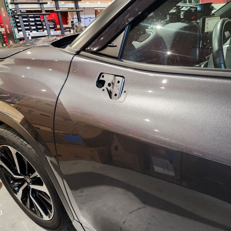
Let’s re-attach them to the vehicle with the three original 10mm nuts. Make sure the wires are cleanly pulled through to the inner side of the door.
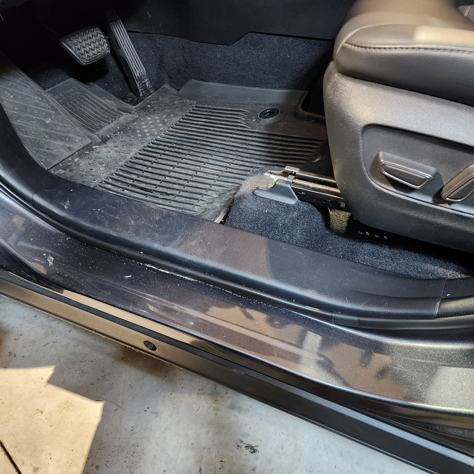
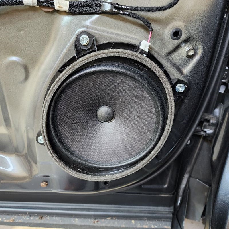
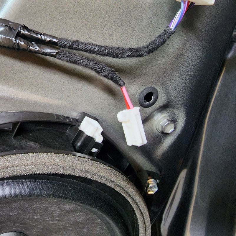
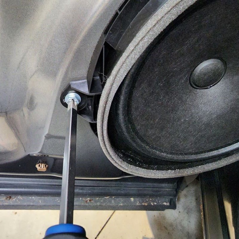
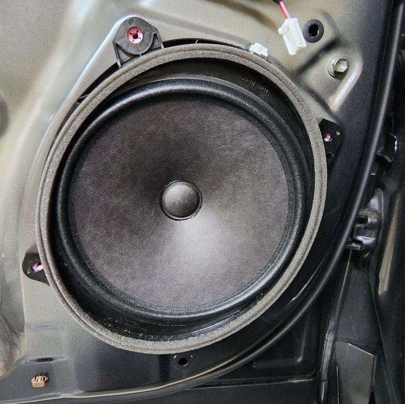
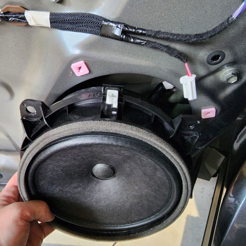
Go ahead and tidy up the wires on the driver door, put the speaker, kick panel and both door cards back on. Remember to plug in all connectors (window controls, speakers, latch/lock Bowden cable terminations) and check that all snap fits are properly engaged.
INSTALL IMAGES


STEP 11
-
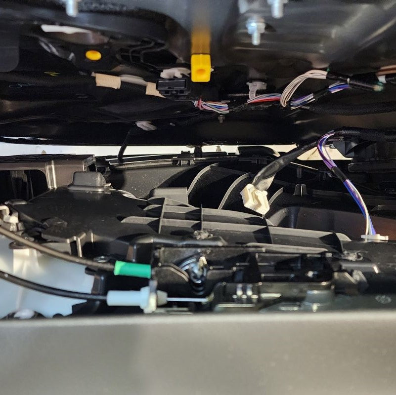
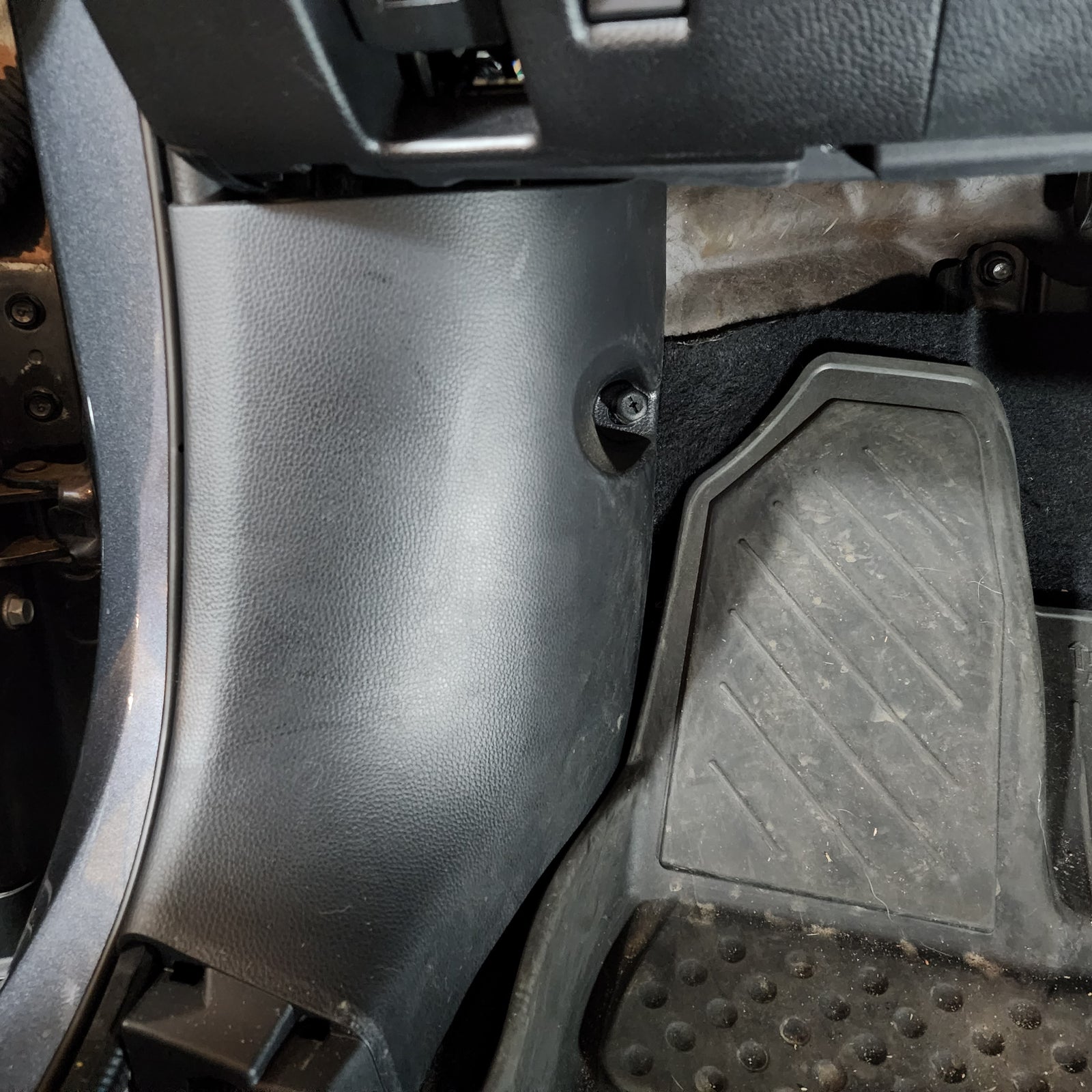
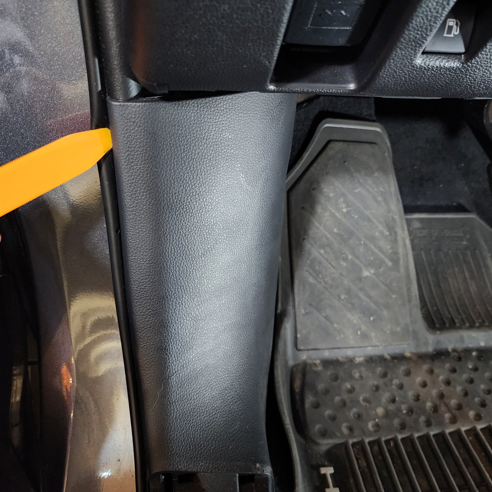
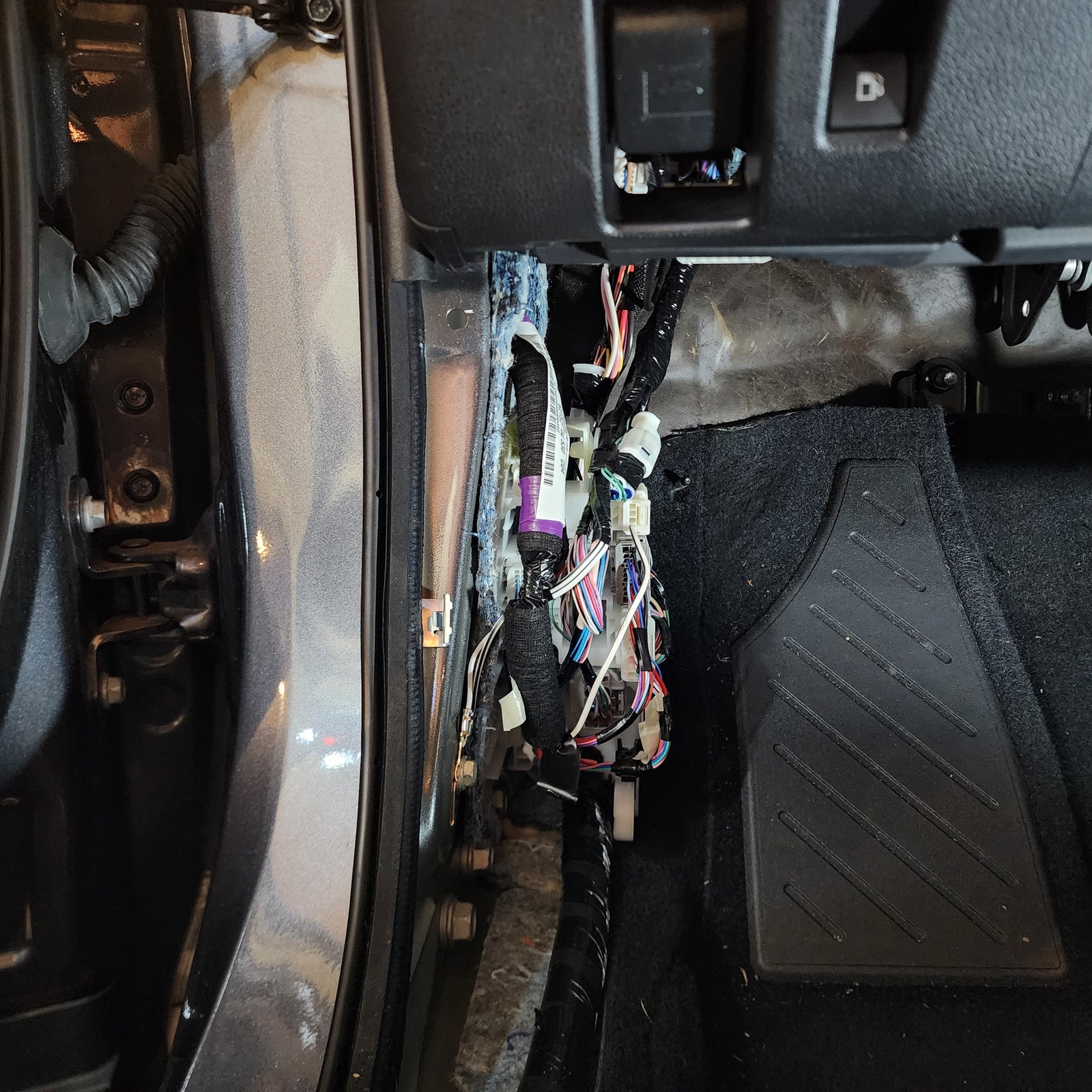
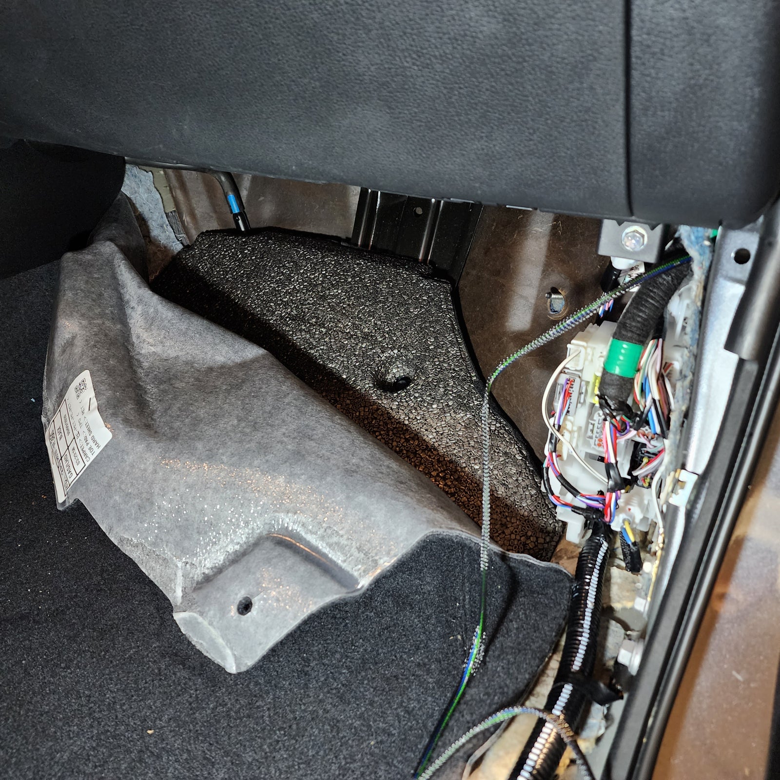
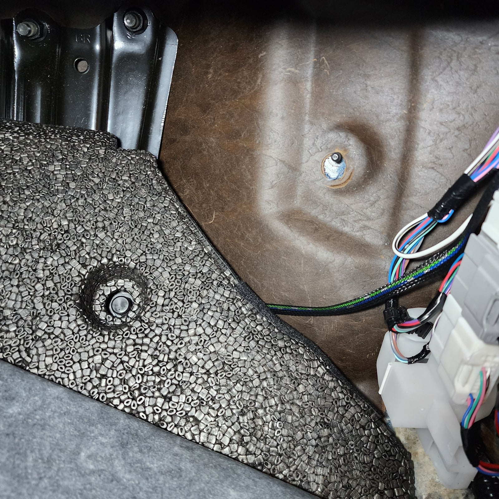
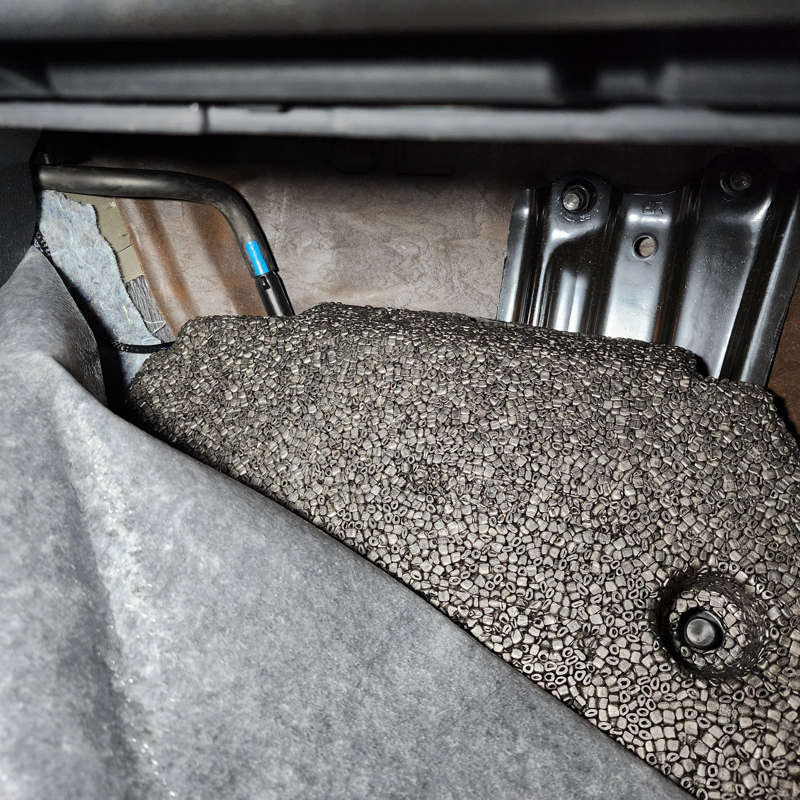
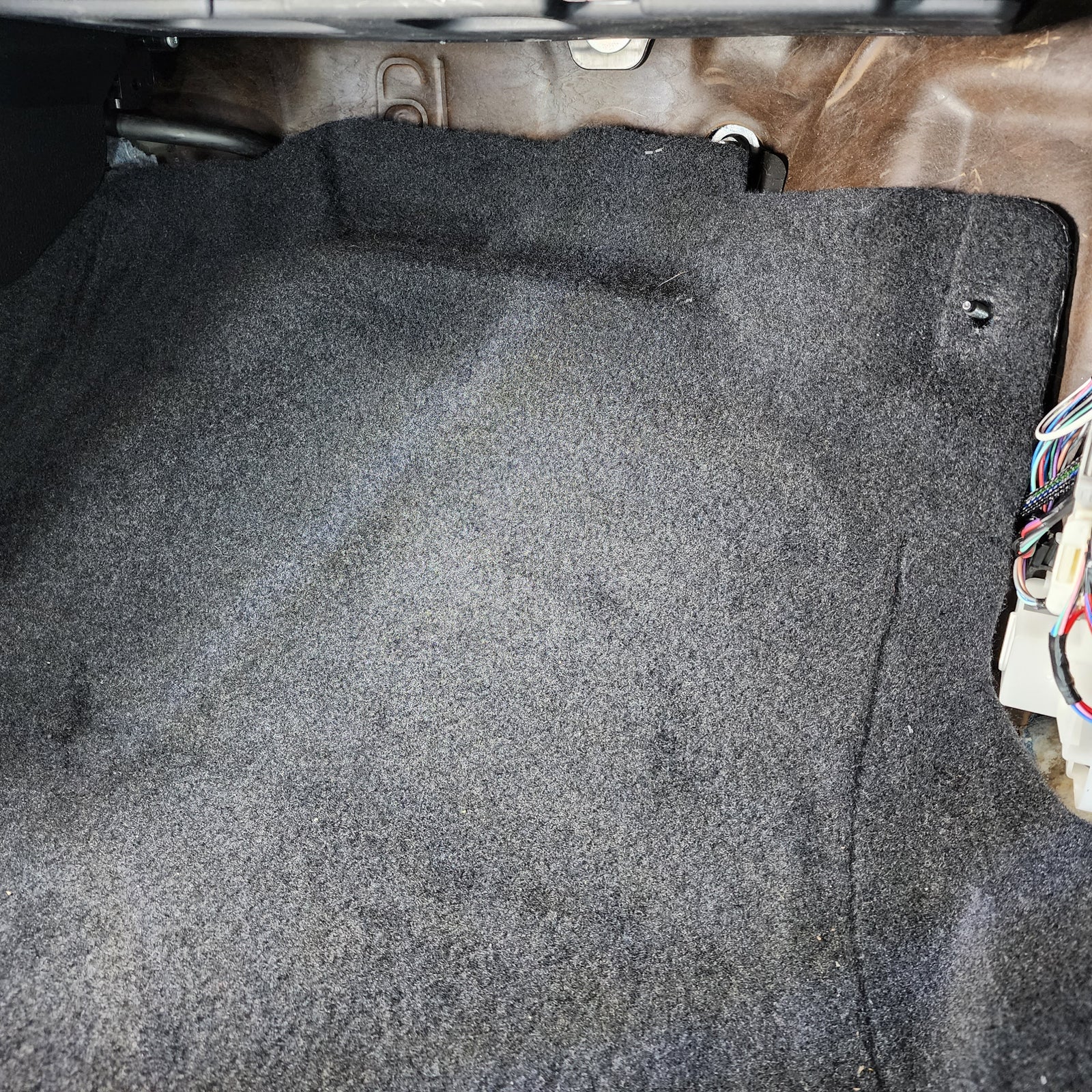
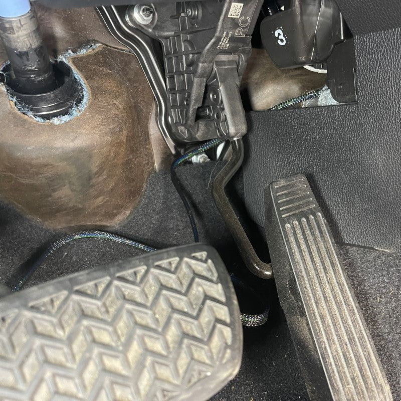
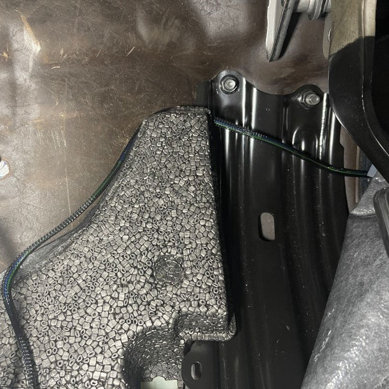
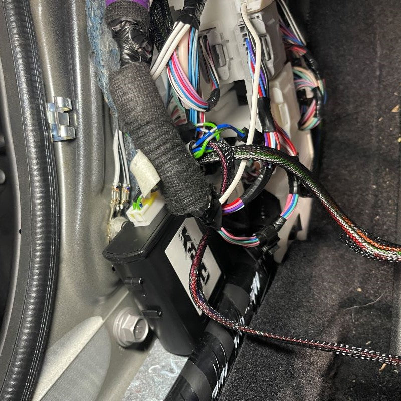
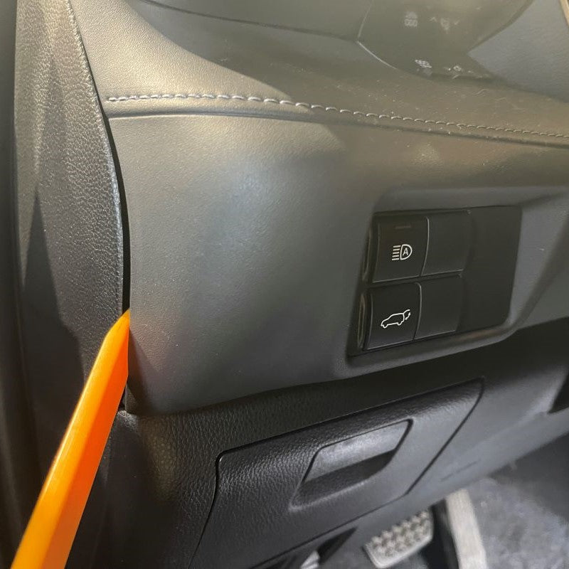
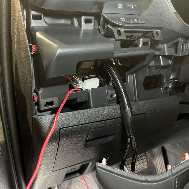
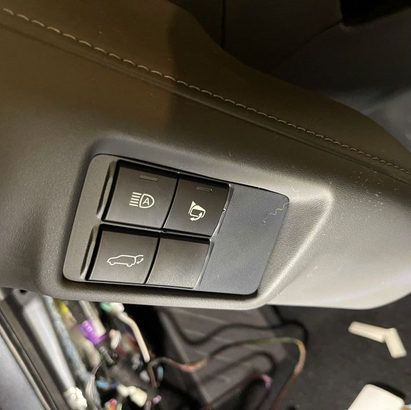
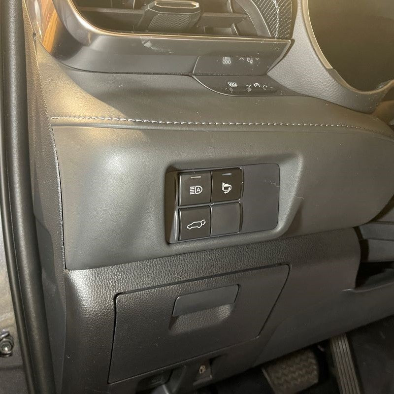
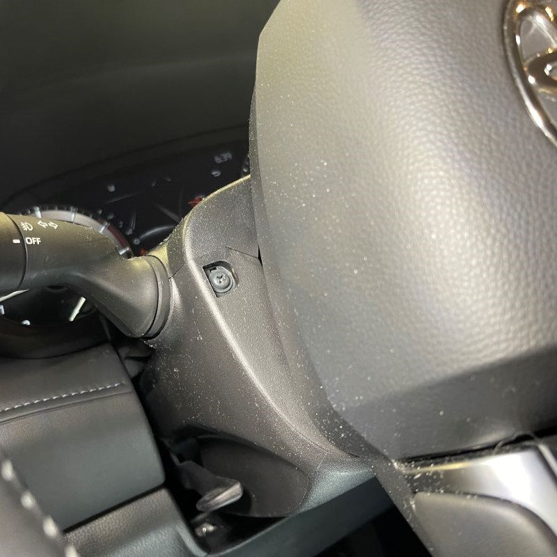
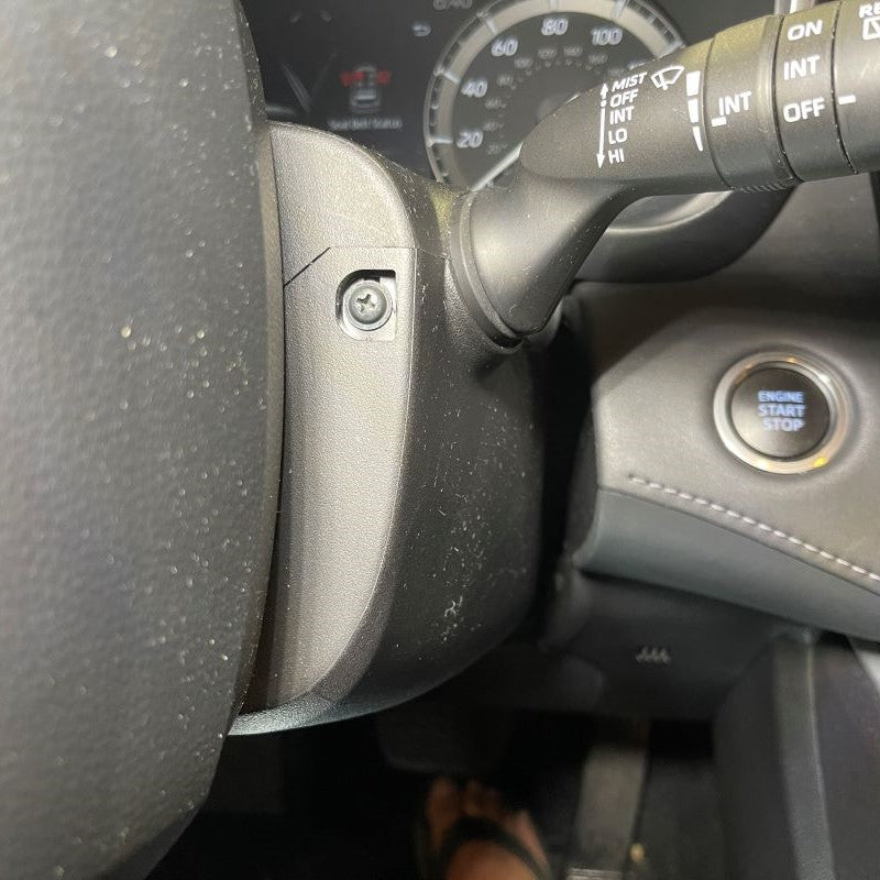
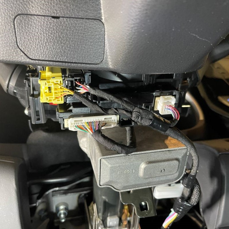
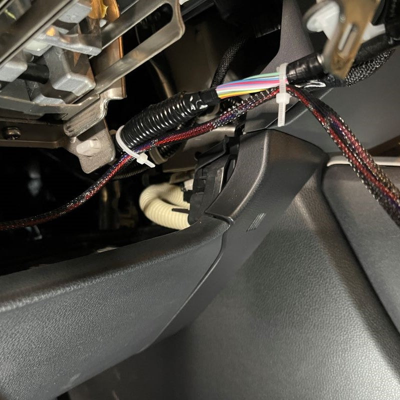
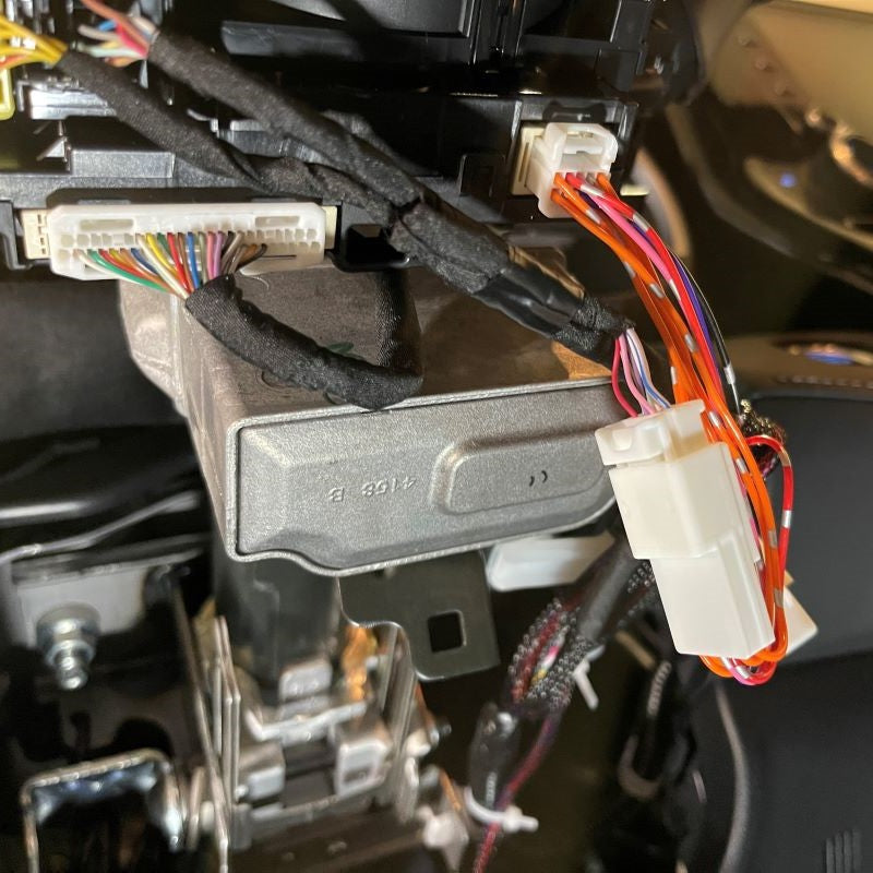
You will have to remove the steering column cover to locate the last connector on your new wire harness. Please follow the images below for guideance.
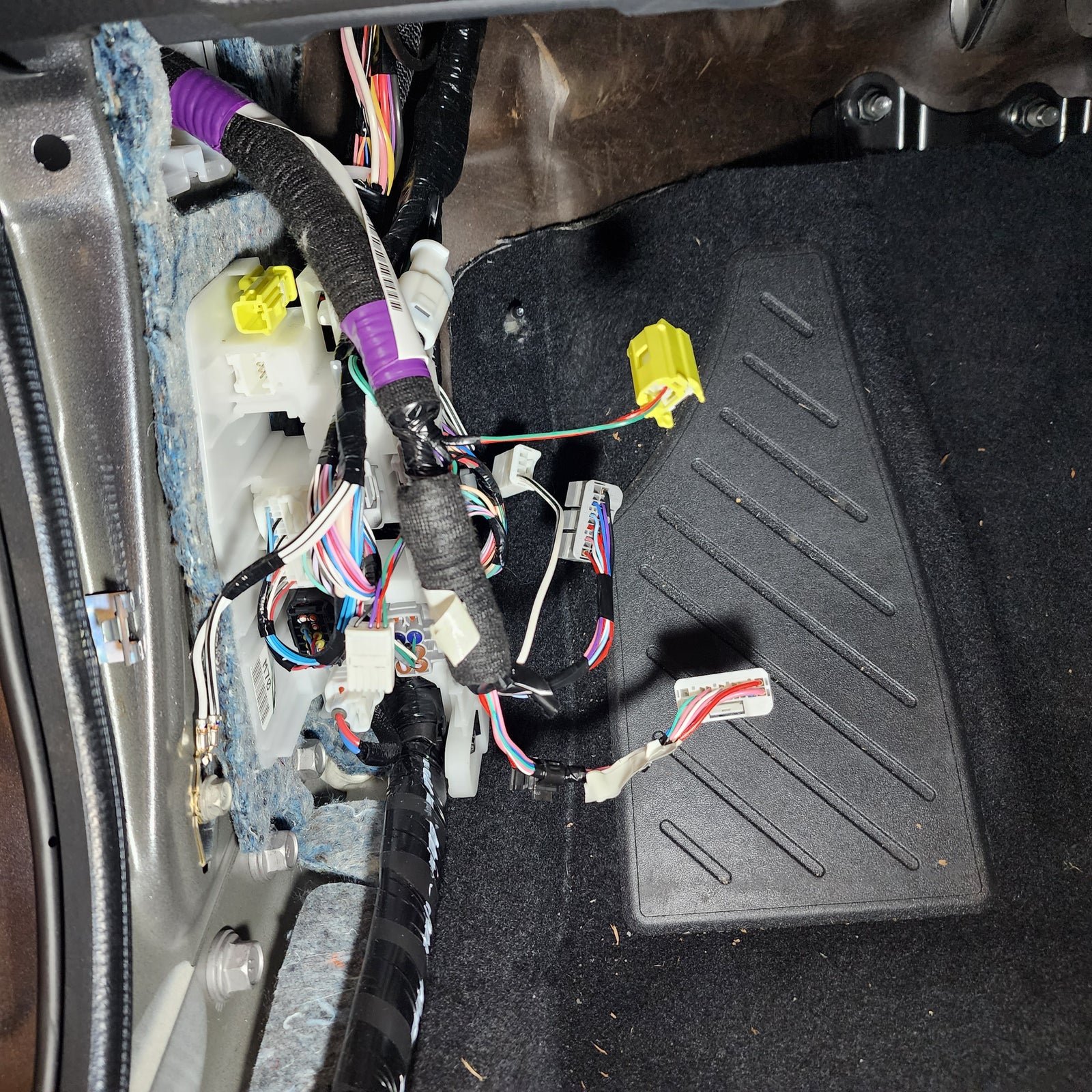
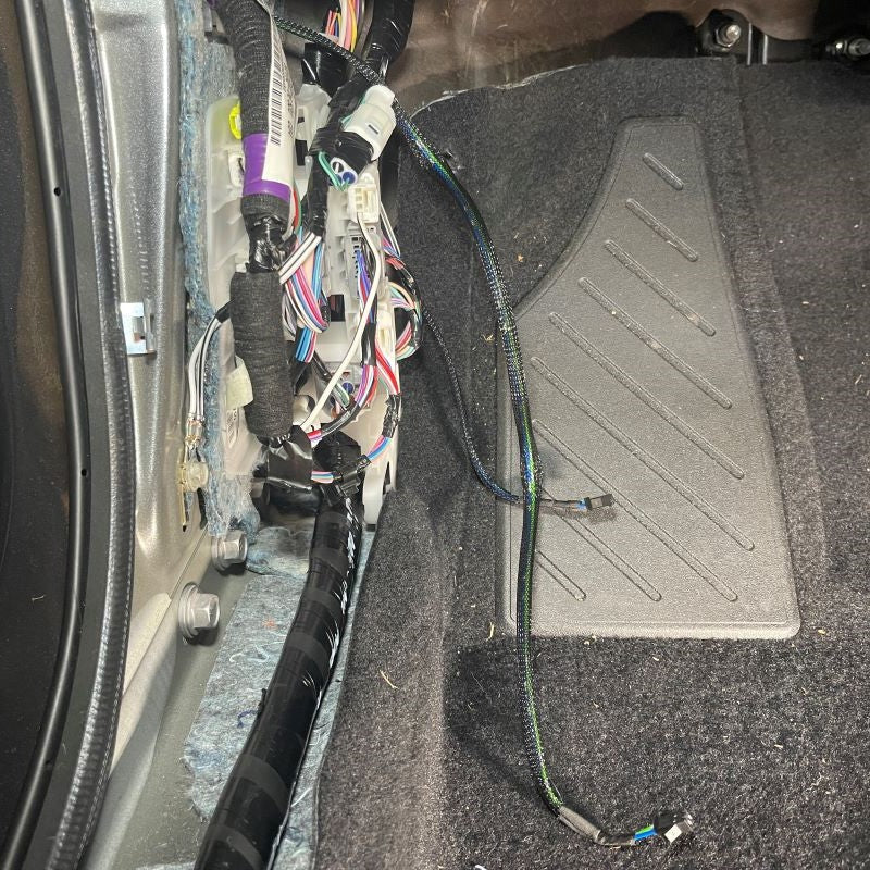
The one fuse will need to plug into your choice of constant 12V power source under your dash. The rest of the wire harness is 100% plug-n-play.
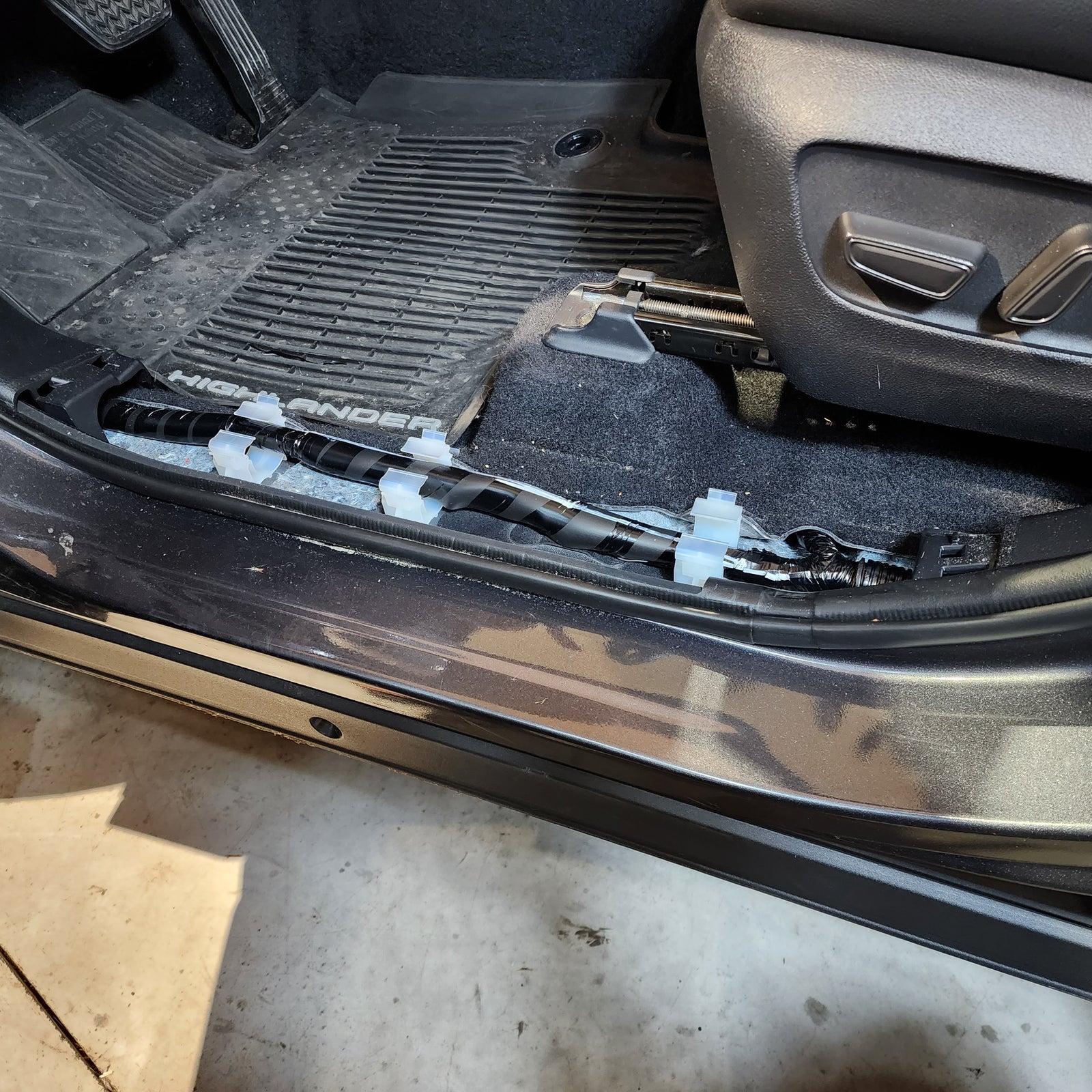
Once you run the wire harnes across the cab and repeat the process that you just completed on the driver side door to the passenger door, you are done with the install.
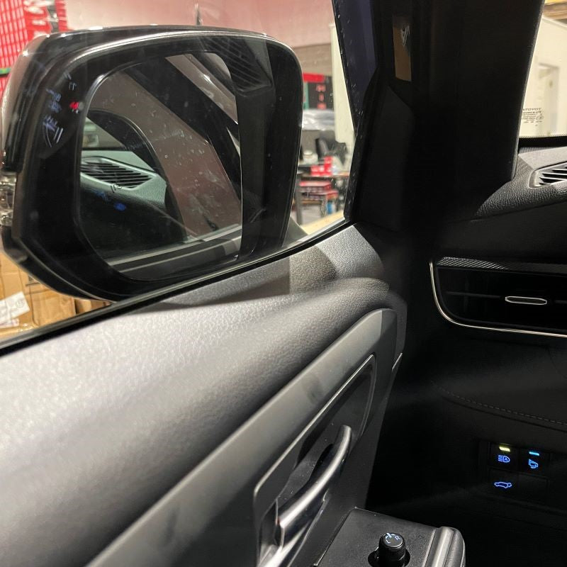
All you need to do is test your new setup!
INSTALL IMAGES


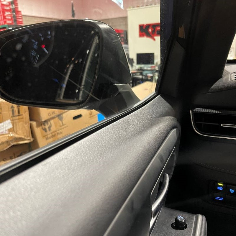


STEP 12
-
Enjoy your New Power Folding Mirrors!